background image

 12

Wiring Diagrams

 13

Enrolling Door Controls

Wired 485 connections

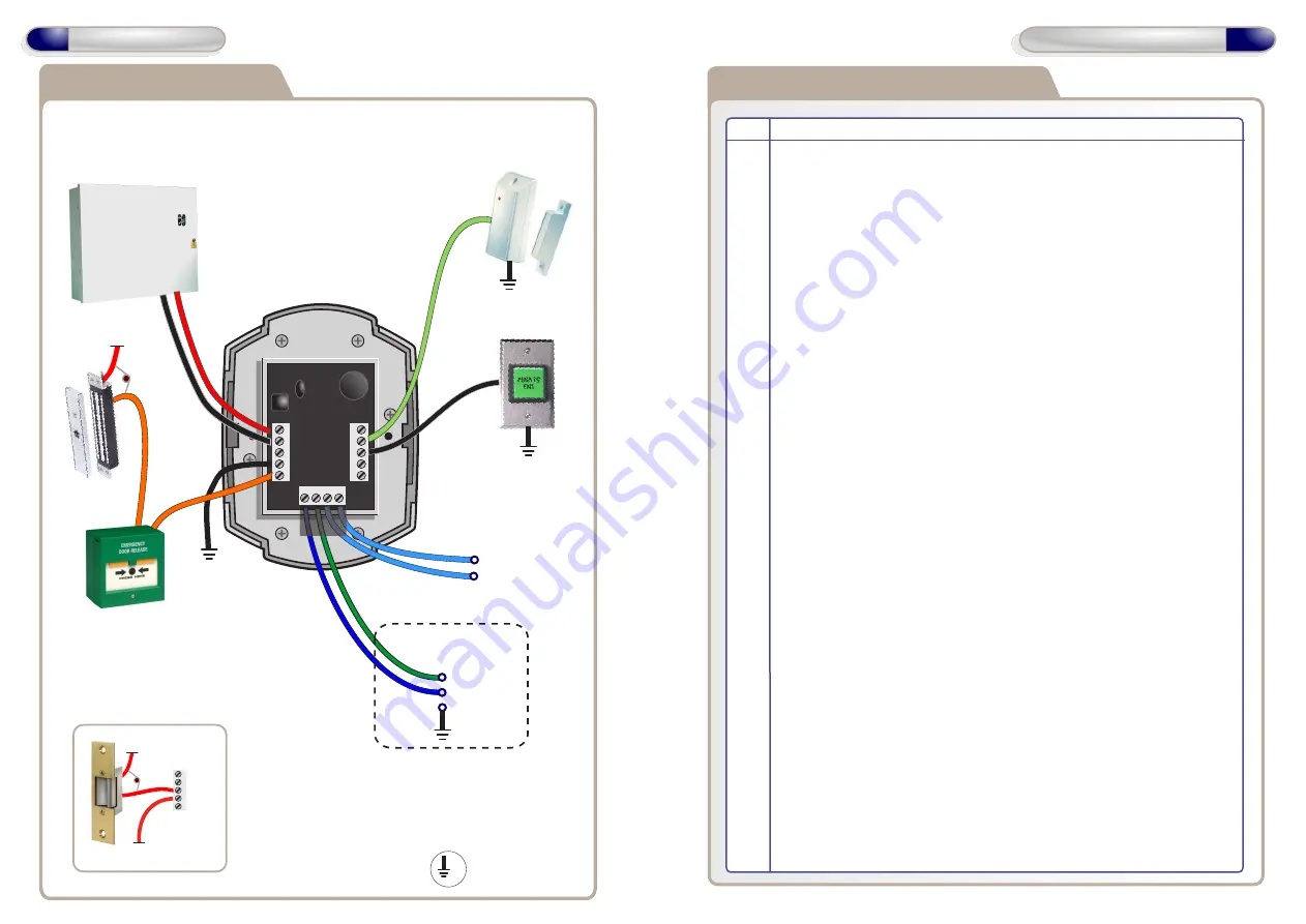
Wiring for StrikeLock only using 12 - 24VAC supply

Note: All OV shown in the
diagram are connected to
OV of the Door Control.

0V

12V
0V
NO
COM
NC

12 - 24 VAC

12 - 24 VAC

   16V
Varistor

12V
0V
NO
COM
NC

IP3
IP2
IP1

OP1
OP2

12V Linear

Power supply

Door

Contact

0V

0V

Door

Exit Button

A

B

0V

Note : Used ONLY for

Wired 485 Network
      Connections.

12V

   16V
Varistor

Door

MagLock

Break Glass

Unit

Volt Free

Tamper Contacts
1 and 2

A

B

0V

Note : Used ONLY for

Wired 485 Network
      Connections.

A

B

T

AMP

T

AMP

Adding Door Controls Overview

Step    Description

   1

Install and Wire each Door Control

   2

Default each Door Control

   3

On PC application - Doors Tab
Click on Add New Door to add a new door to the system

   4

Enrolling On a New System Install:
On PC application - Controller Tab - Wireless Network
Click on Create New Network.
Continue with Step 5

   5    

Enrolling On an Existing System:
On PC application - Controller Tab - Wireless Network
Click Allow Doors to Join.

   6 

Each new Door Control will beep the next available address on the
system

   7

Press a key or present a Fob to assign this address to any Door
Control. Continue with steps 6 & 7 until all new Door Controls are
assigned an address on the system.

   8

After all Door Controls are assigned an address:
On PC application - Controller Tab - Wireless Network
Click on Secure Network.
This secures the wireless network.

    9

On PC application - Doors Tab,
Configure each Door Control with

desired settings.

0V

Содержание Wi-Pin & Prox

Страница 1: ...or Controls Wi Pin Prox Wi Pin Wi Prox Other products from GSD Installation User Manual V2 06 Global Security Devices Ltd No 3 Broomhill Business Complex Tallaght Dublin 24 Ireland Phone 353 1 524 269...

Страница 2: ...of the Door Control 2 Replace the Defaulting Link Jumper on the Door Control 3 Remove the Defaulting Link Jumper immediately after the Green LED turns ON It will take 5 seconds to switch ON 4 This wi...

Страница 3: ...ity screws provided Both Security Caps are then clipped onto the Door Control To attach Security Caps Simply align the tabs into holes and push on until click is heard Surface Mounting Security Caps 5...

Страница 4: ...12 24VAC supply Note All OV shown in the diagram are connected to OV of the Door Control 0V 12V 0V NO COM NC 12 24 VAC 12 24 VAC 16V Varistor 12V 0V NO COM NC IP3 IP2 IP1 OP1 OP2 12V Linear Power supp...

Страница 5: ...ontact 0V Arm Alarm Input Arm Output N O Alarm Panel Alarm Panel Notes Common OV from the Intruder Alarm Panel and the OV from the Door Control to avoid any ground loop issues Only the Manager User ca...

Страница 6: ...0V NO COM NC IP3 IP2 IP1 OP1 OP2 12V Linear Power supply A B TAMP TAMP Interlock OP to Interlock IP on 2nd Door Interlock IP from Interlock OP on 2nd Door Door Contact 0V 0V Door Exit Button Select t...

Страница 7: ...efault each Door Control 3 On PC application Doors Tab Click on Add New Door to add a new door to the system 4 Enrolling On a New System Install On PC application Controller Tab Wireless Network Click...

Страница 8: ...ed an address all unassigned Door Controls will start to beep the next available address 3 When all doors are assigned Click Secure Network Assigning a Door Address on a Wired 485 Network Step Descrip...

Отзывы: