background image


Puma II User’s Guide                                2-1 

Chapter 2  Set Up 


2.1 Setting Up 
 
CAUTION! 


™


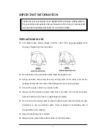
At least two or more persons holding the 

Puma II 132S

 at its bottom surface on         

the left and right sides when you unpacking, installing or relocating the cutter.   

™


Make sure the power switch is off before installing the cutting plotter.


Notice!


Choosing a proper place before setting up the cutting plotter 


Select a proper location which meets the following conditions.


™


The machine can be approached easily from any direction.


™

  Keep at least 60 cm space in front and behind the machine. 

™

  Make sure the cutter is placed on a flat, level and sturdy surface 

™

  The working temperature should be between 

5 and 40

(41-104

o

F)

 in the workshop. 

™

  The relative humidity should be between 

30% and 70%

 in the workshop. 

™

  Protecting the machine from dust and strengthen air current. 

™

  Preventing the machine from direct sunlight. 


Содержание PII-132S

Страница 1: ...Puma II users manual...

Страница 2: ...de installation 2 6 2 5 Media loading 2 9 2 6 Tracking performance 2 15 2 7 Dip switch setting 2 16 2 8 Power on 2 18 2 9 On Off line key 2 19 2 10 Pause key 2 19 2 11 Repeat key 2 19 2 12 Data clear...

Страница 3: ...5 1 5 3 Clearning the pinch rollers 5 2 Chapter 6 Troubleshooting 6 1 6 1 If the cutting plotter cannot operate 6 1 6 2 Light indicators 6 1 6 3 Cutting quality problem 6 5 Appendix 1 Specifications o...

Страница 4: ...fly out During operation keep away from any moving parts of the cutter such as the carriage drums Also be careful that clothing and hair do not be caught Connect the power cable to a grounded outlet...

Страница 5: ...tically according to set of the dip switch usually the presetting is EDGE media type 4 Off line condition Plotter is not ready to receive data from computer Press ON OFF LINE key the LED above the key...

Страница 6: ...nt OFFSET is the distance that the blade tip is displaced from the centerline of the blade II Protrusion Length of the Blade Length of protrusion t1 t 2 2 but for yourconvenience you may just make it...

Страница 7: ...on CD 2 Printer Cable 3 AC Power Cable 4 RS232 Cable 5 Blade Holder Fiber Tip Pen 6 Cutting Strip Pad 7 Safe Blade 8 USB Cable 9 Error Correct Function Sticker 10 Roll Base only for PII 30 60 11 Tweez...

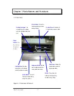
Страница 8: ...uide line marks Cutting Carriage This unit performs the cutting with the installed blade and pen Grid Drum Moves the media back and forth during operation Control Panel Consists of 10 control keys and...

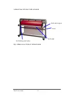
Страница 9: ...1 2 Back View of Puma II 132S with stand Roll holder support Roll Holder guide bushes Stand Roll holder Fig 1 2 Back view of Puma II 132S with stand Puma II users manual 1 2...

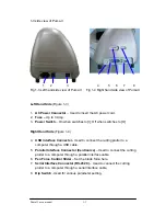
Страница 10: ...nd Side Figure 1 4 4 USB interface Connector Used to connect the cutting plotter to a computer through a USB cable 5 Parallel Interface Connector Centronics Used to connect the cutting plotter to a co...

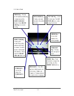
Страница 11: ...ain the ON OFF LINE LED will be off PAUSE Key This key can temporarily halt cutting in progress and the ON OFF LINE LED flashes Press ON OFF LINE Key can resume cutting REPEAT Key Press this button to...

Страница 12: ...before setting up the cutting plotter Select a proper location which meets the following conditions The machine can be approached easily from any direction Keep at least 60 cm space in front and behin...

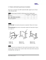
Страница 13: ...hexagon screw driver 1 1 M6 wrench spanner 1 1 Step 2 Puma II 60 stand There are three components to assemble it Please refer to Figure 2 1 Puma II 132S stand There are four components to assemble it...

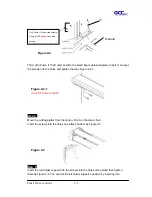
Страница 14: ...arton Put it on the stand then Insert the screws into the holes on plotter s bottom as Figure 2 3 Step 5 Insert the roll holder support with the screws into the holes of the stand then tighten them as...

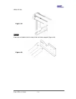
Страница 15: ...Puma II User s Guide 2 4 different holes Step 6 Place two roll holders into the holes in the roll holder support Figure 2 5 Figure 2 5 Figure 2 4...

Страница 16: ...switched off when connecting the cable Warning Connecting the Power Supply Ground the unit with the ground wire Insert the plug male into a grounded power outlet Insert the other end female of power c...

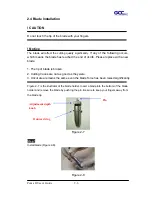
Страница 17: ...place with a new blade 1 The tip of blade is broken 2 Cutting traces are not as good as they were 3 Uncut area remains the same even the blade force has been raised significantly Figure 2 7 is the ill...

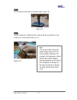
Страница 18: ...tip adjustment screw clockwise or count clockwise Figure 2 10 Figure 2 10 Tips The proper length means the blade s length is about 0 1mm more than film s thickness For example if the thickness of film...

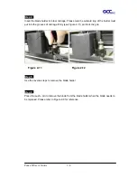
Страница 19: ...holder must put into the grooves of carriage firmly see Figure 2 11 and lock the grip Step 5 Use the reverse steps to remove the blade holder Step 6 Press the push pin to remove the blade from the bla...

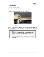
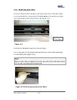
Страница 20: ...slide it under the pinch rollers from either the front side or the backside The alignment rulers on the platen extension will help you to adjust the media precisely Note Be sure that the media must co...

Страница 21: ...to position pinch rollers easily and correctly Figure 2 14 Push the lever backward to lower down the pinch rollers Turn on the power the tool carriage will measure the size of the media automatically...

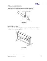
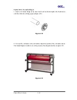
Страница 22: ...a First put the roll media guide bushes on two roll holders Figure 2 16 Option A Recommended Insert the two roll holders into the roll media support set then place the roll media directly between the...

Страница 23: ...of each roll media and tighten the thumbscrew until the roll media is firmly gripped Figure 2 18 2 Then put the roll media on the roll holders Adjust the position of the roll media ensure that media...

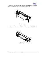
Страница 24: ...on the platen After loading the roll media flatten the media on the platen and hold the front edge of the roll media firmly Figure 2 20 4 Then turn the roll downward to make an equal tension across t...

Страница 25: ...roll media guide bushes on the roll holder to secure the roll media 8 Turn on the power switch and the tool carriage will size the media automatically Then the cutting plotter is ready to work 9 Use t...

Страница 26: ...as follows 1 If the media length is less than 4 m leave the margin of 0 5mm 15mm in the left and right edges of the media see Figure 2 23 2 If the media length is greater than 4m leave at least 25mm...

Страница 27: ...m SW 4 Media Weight Light Heavy Light Media SW 5 Quality Draft Fine Fine SW 6 Smooth Enable Disable Enable SW 7 Auto Unroll Enable Disable Enable SW 8 Media Type Edge Single Edge SW 1 3 OFFSET SETTING...

Страница 28: ...7 AUTO UNROLL Unroll the heavy media at least 50 cm when the next point of movement is located beyond the unrolled position As the media type is Single this function will be disabled SW 8 MEDIA TYPE...

Страница 29: ...the left hand side of the cutting plotter and the POWER LED is on Notice It will take about 10 sec to initialize the machine the cutting plotter is ready to receive data from computer As bellowing is...

Страница 30: ...TA CLEAR key Off line When the machine is in OFF LINE condition the ON OFF LED turn off At this moment you can switch dip setting make cutting test to adjust blade pressure and set new origin Press th...

Страница 31: ...se of the DATA CLEAR key is to clear the data in the buffer memory The DATA CLEAR key can only works under pause or off line condition When use this function the DATA CLEAR LED will light 2 13 Origin...

Страница 32: ...INE key to switch to off line mode 2 Then use arrow keys to move the tool carriage to the position where you will make cut test 3 Press the CUT TEST key to make the cutting test The CUT TEST LED turns...

Страница 33: ...ust the OFFSET setting please refer to paragraph SW1 3 OFFSET SETTING Please also refer to the paragraph About the tool at the beginning of the book to learn the definition of offset Note The new orig...

Страница 34: ...2 15 When Completing the Cutting Job After completing the cutting raise the sheet loading lever then remove the material You can also cut off the extra media with the cutter tool along the knife guid...

Страница 35: ...tomatically 2 Please don t plug in USB cable when you install the driver Parallel Interface Serial Interface USB Interface Figure 3 1 3 1 Universal serial bus Puma II build in USB interface are based...

Страница 36: ...e computer to the cutting plotter Option 1 With proper interface settings the data can be transmitted from your application software package to the cutting plotters directly Option 2 Most cutting soft...

Страница 37: ...o automatically execute MODE command every time you want to output your data at the DOS prompt via serial connection However values in a MODE command should comply with the related requirements of you...

Страница 38: ...urations in your cutting plotter To run this utility simply execute it under Windows Before starting the detection make sure 1 The cutting plotter is at the ON LINE status 2 There is media in the mach...

Страница 39: ...ze Loop Detect DisDetect Scaling and About A Poll Size Clicking the Poll Size will reveal the X Y values In this case the maximum cutting length is 25000mm and the distance between the farthest two pi...

Страница 40: ...Detect and DisDetect Clicking Loop Detect will reveal the value settings of your cutting plotter Figure 4 3 3 Figure 4 3 3 If you want to change the value settings please click DisDetect first Puma I...

Страница 41: ...ent click Loop Detect again You will then be able to see the new values In this case the Force was changed from 200 to 277 see figure 4 3 5 Figure 4 3 4 Figure 4 3 5 Notice One function of the DisDete...

Страница 42: ...ice with the port currently used C Scaling Click DisDetect and then the Scaling key will be enabled Figure 4 3 6 After clicking Scaling a dialog will pop up Figure 4 3 7 Figure 4 3 6 Enter the width a...

Страница 43: ...Figure 4 3 8 After pressing OK the cutting plotter will cut the 50mm2 rectangle again and the following dialog will pop up Figure 4 3 9 Measure the real cutting width and length If it is a 50mm2 rect...

Страница 44: ...asked to key in a password Type in 111 Figure 4 3 11 Figure 4 3 11 Click OK and complete scaling Figure 4 3 12 Figure 4 3 12 D About The About key shows you the version of your cutting plotter s firm...

Страница 45: ...Figure 4 3 13 Puma II User s Manual 4 8...

Страница 46: ...cutting plotter surface with a lint free cloth If necessary clean with a damp cloth or an alcohol immersed cloth Wipe with water to rinse off any residue and dry with a soft lint free cloth Wipe all d...

Страница 47: ...he drum manually while cleaning Refer to Figure 5 1 5 3 Cleaning the Pinch Rollers If the pinch rollers need a thorough cleaning use a lint free cloth or cotton swab to wipe away the accumulated dust...

Страница 48: ...lem Why the cutting plotter does not operate 6 1 If the Cutting Plotter Cannot Operate If your Puma doesn t run please check the following items firstly Does the AC power cord plug in properly Does th...

Страница 49: ...once can also turn off the ERROR LED Warming Indicators ERROR ON OFF LINE REPEAT DATA CLEAR CUT TEST 1 Graph was clipped 2 HPGL 2 command Error 3 Lever up or no media 4 Cannot repeat 5 Communication...

Страница 50: ...ding the same cutting job from the computer again In both conditions press ON OFF LINE key to clear the warming message Warming 5 Communication error Check if the serial USB parallel cables have been...

Страница 51: ...ia or Y motor flash on off Error 1 and 2 Please contact customer service personnel to replace a new SRAM or DRAM Error 3 Check media drum or X motor This message indicates that there might be a proble...

Страница 52: ...Installation the blade of Chpater 2 No Check tool force setting Yes Check tool offset setting No Please refer to 2 13 Cutting Test to adjust the tool force Yes Is there any dirt adhered to the blade...

Страница 53: ...reater Repeatability 0 1mm up to 3 meters certified media Data Buffer Size 4MB Interfaces USB 1 1 Parallel Centronics Serial RS 232C Commands HP GL HP GL 2 Configurable Origin Yes Vector Look Ahead Ye...

Страница 54: ...R The blade is 45 with Red Cap 0 25 mm offset For cutting reflective vinyl cardboard sandblast flock and stencil sharp edge ZZ00221A GCB 360SB The blade is 60 with Green Cap 0 50 mm blade offset For c...

Отзывы: