background image

StellarMark IFII-Series User Manual   

Rev.5.0


19 


3.1.2 

Scan Lens 

The StellarMark

TM 

IFII-series offers 3 to 4 different scan lens size 

options to best suit your marking applications.     

IFII 20JFL 070 

IFII 20JFL 110 

IFII 20JFL 180 

70x70mm 

110x110mm 

180x180mm 

IFII 20SHS 070 

IFII 20SHS 110 

IFII 20SHS 180 

70x70mm 

110x110mm 

180x180mm 

IFII 30JFL 070 

IFII 30JFL 110 

IFII 30JFL 180 

70x70mm 

110x110mm 

180x180mm 

IFII 60JFL 070 

IFII 60JFL 110 

IFII 60JFL 180 

70x70mm 

110x110mm 

180x180mm 


  The smaller field size scan lens will produce a smaller spot size 

with higher marking resolution. 

  The larger field scan lens will produce a larger spot size with 

lower marking resolution. 
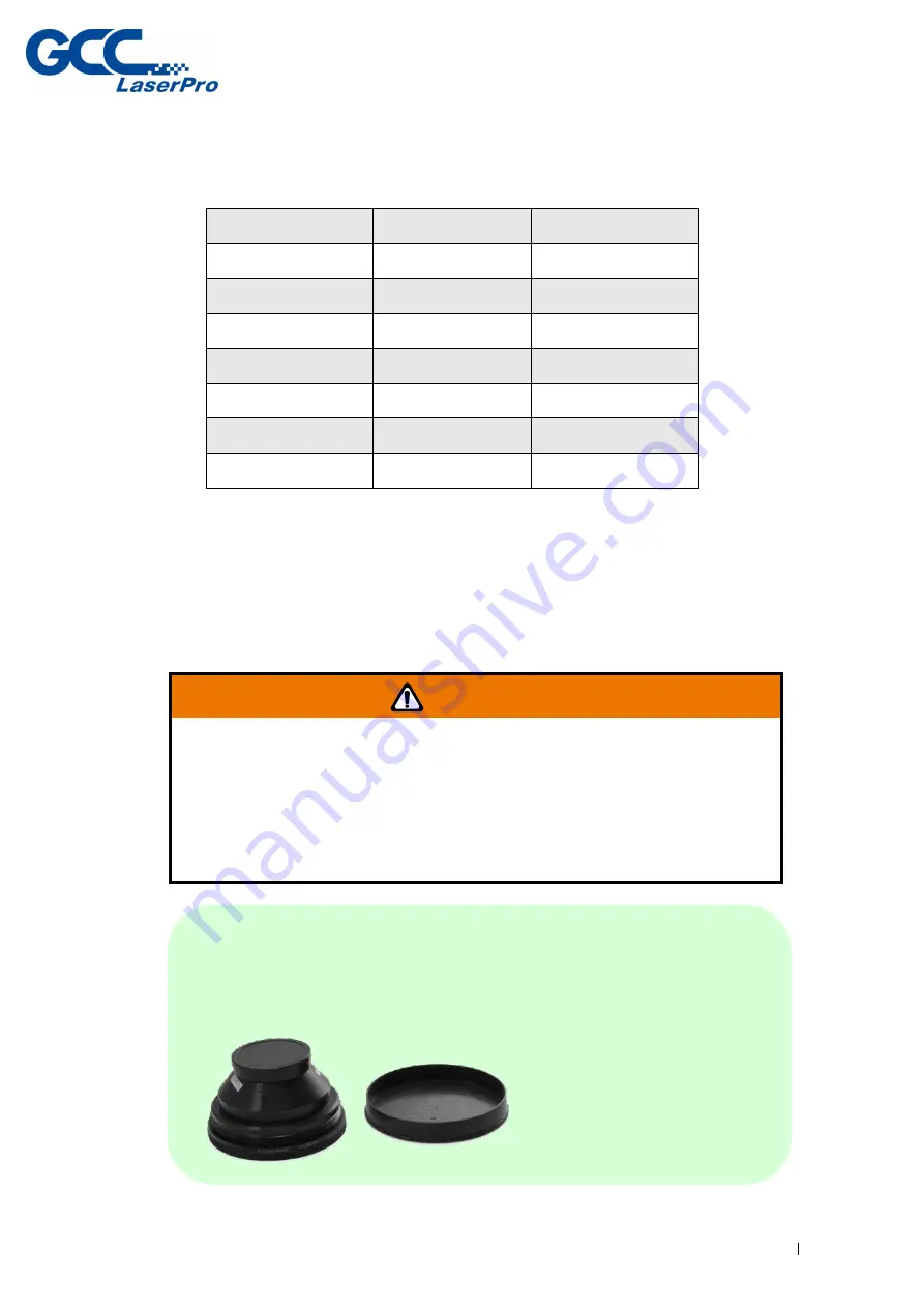


NOTE 

Scan lens is protected by a cover to prevent damage during shipment. 

Always remove the cover prior to use. 


WARNING


The scan lens is very fragile and must be careful while the cleaning 

and installing. 

Defective  or  unworkable  scan  lens  due  to  abuse,  mishandling, 

misuse,  accident,  alteration,  negligence,  improper  installation, 

deficient cleaning or other causes will not be covered in the warranty.


Содержание LaserPro StellarMark IFII Series

Страница 1: ...4F No 236 Fude 2nd Rd Xizhi Dist New Taipei City 22151 Taiwan 886 2 6616 6692 Fax 886 2 2694 6875 Version 5 0 Released Feb 2020 StellarMark IFII Series User Manual IF Series...

Страница 2: ...arMark IFII Series User Manual Rev 5 0 i Release Note Version Release Date Change Note 4 0 Jan 2019 Modify chapter 4 2 Pyramid focus tool Modify chapter 4 3 Manual focus tool 5 0 Feb 2020 Add IFIIS mo...

Страница 3: ...Foot Print 24 CHAPTER 4 WORKING DISTANCE 26 4 1 Recommended Working Distance 26 4 2 Pyramid Focus Tool 27 4 3 Manual Focus Tool 31 CHAPTER 5 MACHINE SETUP 33 5 1 Cable connection 34 5 2 Powering Up th...

Страница 4: ...ROR MESSAGE 92 CHAPTER 9 EXTERNAL CONTROL 94 9 1 I O Pin Assignment 95 9 2 Laser Working Flow Chart 98 9 3 Laser Reaction Timing Diagram 99 CHAPTER 10 BASIC MAINTENANCE 101 10 1 Regular Spot Check 102...

Страница 5: ...StellarMark IFII Series User Manual Rev 5 0 1 Chapter 1 Safety Principles of a Fiber Laser Safety Ratings The Safety Interlock System Safety Labels Safety Measures Operating Environment...

Страница 6: ...logy fiber laser is immune of misalignment and does not request any adjustment during operation 1 2 Safety Ratings StellarMark IFII series laser marker emits intense and INVISIBLE laser radiation with...

Страница 7: ...rds all fixed or removable covers that allow access to laser beam must have appropriate laser warning labels attached to them These warning labels must be clearly visible to the operator prior to remo...

Страница 8: ...all the safety labels and their locations on the machine Product Label This label is located at the side panel of machine All the product information such as Serial Number Model Number Laser Power an...

Страница 9: ...StellarMark IFII Series User Manual Rev 5 0 5...

Страница 10: ...StellarMark IFII Series User Manual Rev 5 0 6...

Страница 11: ...ut the equipment The following warning labels are placed on the laser system for your safety Do not remove these labels for any reason If the labels become damaged or have been removed for any reason...

Страница 12: ...with all the necessary information to be aware of in every operation Invisible laser radiation when operation Avoid eye or skin exposure direct to laser radiation The scan lenses are fragile Take extr...

Страница 13: ...urself with the warning labels located on both your laser system and in this manual Never leave the machine unattended during the laser cutting and marking process The laser may ignite combustible mat...

Страница 14: ...and maintain your machine according to our cleaning and maintenance instructions Doing so will ensure a machine that will operate effectively and safely over a long period of time 1 6 Operating Enviro...

Страница 15: ...temperature is near the dew point Setup the machine to be apart from the wall for at least 40cm 1 5 feet Choose a flat surface that is not exposed to high levels of vibration Be sure that your mountin...

Страница 16: ...StellarMark IFII Series User Manual Rev 5 0 12 Chapter 2 Unpacking Content Unpacking and Unloading Accessories Checklist...

Страница 17: ...ontrol Unit software and all of the necessary accessories in an accessory kit NOTE Please save the original shipping crate in case it is needed for future transportation or product service Control Uni...

Страница 18: ...nual Rev 5 0 14 2 2 Accessories Checklist Please check to make sure that all of the following items are included within the accessory box If any of the following items are missing immediately contact...

Страница 19: ...ts Package 1 8 Lens Parameter List 1 9 GCC Promise Card Set 1 10 Focus Tool 1 11 1064nm Goggle YG3 900 1 12 AC Power Cable Europe 1 AC Power Cable US 1 AC Power Cable Australia 1 13 USB Cable 1 8M 1 1...

Страница 20: ...StellarMark IFII Series User Manual Rev 5 0 16 Chapter 3 Mechanical Overview Laser Marker Control Unit Foot Print...

Страница 21: ...ries User Manual Rev 5 0 17 Before complete the installation it is a good idea to become more familiar with the machine s features and components 3 1 Laser Marker 3 1 1 LED Panel LED Panel Laser Tube...

Страница 22: ...On and Power on of the laser marker Over Temp When the red LED light is on the laser marker will stop firing Please turn off the master power of the laser marker and re start it when the operating te...

Страница 23: ...110 IFII 60JFL 180 70x70mm 110x110mm 180x180mm The smaller field size scan lens will produce a smaller spot size with higher marking resolution The larger field scan lens will produce a larger spot si...

Страница 24: ...on to stop the laser in an emergency To reset this button rotate it to the direction of an arrow Key Switch Optical Fiber Cable Power On Signal Ready Signal Laser On Laser Marker Power USB Port Rotary...

Страница 25: ...e back of Control Unit and they are the signal transmitting bridges between StellarMark and automation devices such as the conveyer for automation controls 8 Output signal pins and 8 Input signal pins...

Страница 26: ...r automation devices 3 2 3 Rotary Attachment Connector Rotary Attachment port connects StellarMark optional Rotary Attachment to IFII series laser marker it allows laser marker to process precise 360...

Страница 27: ...ual Rev 5 0 23 3 2 5 Mark On Fly Terminal Connector Mark On Fly Terminal connects laser marker to an external encoder of a conveyor system It allows IFII series laser marker to do non stop on the fly...

Страница 28: ...StellarMark IFII Series User Manual Rev 5 0 24 3 3 Foot Print 3 3 1 Laser Marker Foot Print 3 3 2 Control Unit Foot Print...

Страница 29: ...StellarMark IFII Series User Manual Rev 5 0 25...

Страница 30: ...istance Two Point Focus Finder Focus Tool 4 1 Recommended Working Distance Due to the characteristics of the scan lens a certain distance between the marking object and scan lens has to be set for an...

Страница 31: ...tance on StellarMark IFII series You will find the pyramid focus tool is located on bottom of the laser marker NOTE In order to achieve the best output quality the working distance must set precisely...

Страница 32: ...OTE Fixed length will be varied depend on the size of scan lens The fixed length of Pyramid Ruler equals the recommended working distance and you will no need to adjust the length NOTE 1 With this too...

Страница 33: ...1 Calibrate the Pyramid Focus Tool When changing to different size scan lens for different applications the calibration of Two Point Focus Finder position is required Perform the adjustment per follo...

Страница 34: ...Step 2 Place the focus tool on the Z axis table or any table surface for marking objects adjust the Z axis to allow the top of the focus tool to align with the bottom of the galvo head to define the o...

Страница 35: ...r Manual Rev 5 0 31 Step 4 Calibration is completed 4 3 Manual Focus Tool The focus tool offers you the most accurate focus distance All you need is place the bottom of the focus tool at the position...

Страница 36: ...to allow the top of the focus tool to align with the bottom of the galvo head to create the optimized focus distance WARNING The length of Focus Tool is calibrated with corresponding scan lens Do not...

Страница 37: ...StellarMark IFII Series User Manual Rev 5 0 33 Chapter 5 Machine Setup Cable Connection Powering Up the Machine...

Страница 38: ...Cable connection Step 1 Connect the Laser Marker power cable between the Control Unit and the Laser Marker Step 2 Connect the SCSI cable between the Control Unit and Laser Marker Step 3 Connect the US...

Страница 39: ...an external device like conveyor Step 5 Plug the rotary attachment cable between Control Unit and the rotary attachment device if you have this optional item in hand Step 6 Plug the software keypro to...

Страница 40: ...roerly grounded outlet Step 2 Plug the computer to AC outlet Step 3 Connect the female end of the Control Unit power cord to the power inlet located on the Control Unit s rear side NOTE The Stellar Ma...

Страница 41: ...laser marker re start G Mark marking software is required due to the connection between computer and control box is disconnected when power off therefore the marking software is unable to control the...

Страница 42: ...Turn the key switch on so you will be able to fire the laser OFF Left ON right Step 3 Press LASER ON button The indicator light will alternately turn on and ready to lasing NOTE After finishing marki...

Страница 43: ...Series User Manual Rev 5 0 39 Chapter 6 Software Setup Recommended Computer Configuration Software Installation for Windows System Software Installation for MAC System Change the Series and Model Typ...

Страница 44: ...sing a Windows based system with the following minimum requirements Computer Configuration CPU Intel Pentium 1GHz or above DRAM 1GB RAM or above CDROM One CD ROM disk drive HDD 500 MB of free hard dri...

Страница 45: ...ps Step 1 Take out the G Mark installation CD from the accessories kit Step 2 Insert the G Mark installation CD into the CD ROM drive Wait a few seconds for the CD Manager to begin the Setup automatic...

Страница 46: ...StellarMark IFII Series User Manual Rev 5 0 42 Step 4 Set the destination directory and click Next Step 5 Select Next Step 6 Installing...

Страница 47: ...StellarMark IFII Series User Manual Rev 5 0 43 Step 7 At 95 completion of the installation the ModelManger window will show up Step 8 Select your series model type...

Страница 48: ...StellarMark IFII Series User Manual Rev 5 0 44 Step 9 Click OK...

Страница 49: ...you will find Laser marking controller at the lower right hand corner on your computer screen this indicates the computer is able to communicate with StellarMark NOTE If Laser marking controller is no...

Страница 50: ...ser Manual Rev 5 0 46 A Please go to Control and click on System B Please check if there is any USB device with warning sign from the below chart C Then click on USB Driver and click on right mouse bu...

Страница 51: ...ries User Manual Rev 5 0 47 D Click on Browse my computer for driver software E Key in the specific path C Program Files G Mark Lib Drivers MC1 and press Next F Press Finish and now you can activate t...

Страница 52: ...tellarMark machines by purchasing the Parallels Desktop software which allows you to install Windows OS in MAC computers and run Windows based software under MAC computer and output with G Mark Step 1...

Страница 53: ...StellarMark IFII Series User Manual Rev 5 0 49 Step 3 Read Software License Agreement and press Accept to continue installation Step 4 Enter your Mac OS X User Name and Password then press OK...

Страница 54: ...StellarMark IFII Series User Manual Rev 5 0 50 Step 5 Press Active Step 6 Press OK when activation is complete...

Страница 55: ...StellarMark IFII Series User Manual Rev 5 0 51 Step 7 Register Parallels Desktop Step 8 Press Register and OK to complete the installation of Parallels Desktop...

Страница 56: ...k IFII Series User Manual Rev 5 0 52 Step 9 Open Parallels Desktop in the Applications folder then choose File New Step 10 Press Install Windows from DVD or image file then press continue to install w...

Страница 57: ...StellarMark IFII Series User Manual Rev 5 0 53 Step 11 Select CD ROM drive with the Windows installation CD Step 12 Enter the Windows OS product key...

Страница 58: ...ark IFII Series User Manual Rev 5 0 54 Step 13 Select how you would like to run your Windows program Step 14 After the prior setting is complete the windows OS installation procedure will start automa...

Страница 59: ...tion for windows system to install G Mark G Mark Library NOTE Once the G Mark software installation is completed you can start to open a new file to edit or import an existing file to G Mark for laser...

Страница 60: ...wing an error message when you open the G Mark software program Please perform the following steps to solve problem Error message 1 Please insert KeyPro 1 Fix 1 Please close the G Mark software progra...

Страница 61: ...StellarMark IFII Series User Manual Rev 5 0 57 Step 3 Please check if there is any USB device from the below chart Step 4 Then click on USB Driver and click on right mouse button and update the driver...

Страница 62: ...StellarMark IFII Series User Manual Rev 5 0 58 Step 5 Click on Browse my computer for driver software Step 6 Key in the specific path C Program Files G Mark Lib Drivers MC1 Then press Next...

Страница 63: ...can reopen the G Mark software Error message 2 Controller not found Fix 1 Reconnect the USB cable between a PC or Laptop and the Control unit and then reopen the G Mark software program Fix 2 Update...

Страница 64: ...StellarMark IFII Series User Manual Rev 5 0 60 Step 2 Select Device Manager Step 3 Please check if there is any USB device from the below chart...

Страница 65: ...StellarMark IFII Series User Manual Rev 5 0 61 Step 4 Then click on USB Driver and click on right mouse button and update the driver Step 5 Click on Browse my computer for driver software...

Страница 66: ...StellarMark IFII Series User Manual Rev 5 0 62 Step 6 Key in the specific path C Program Files G Mark Lib Drivers MC1 Then press Next Step 7 Press Finish and now you can activate the G Mark software...

Страница 67: ...of the device manager but cannot update the driver We recommended you disable the driver signature enforcement on safe mode please perform the following steps Step 1 Select the Start button Step 2 Typ...

Страница 68: ...StellarMark IFII Series User Manual Rev 5 0 64 Step 5 Select Troubleshoot Step 6 Select Advanced Options...

Страница 69: ...StellarMark IFII Series User Manual Rev 5 0 65 Step 7 Select Startup Settings Step 8 Select Restart...

Страница 70: ...ual Rev 5 0 66 Step 9 A menu will appear where you can press F7 on your keyboard to choose Disable driver signing enforcement Step 10 After rebooting go to C Program Files x86 G Mark Lib Drivers MCx a...

Страница 71: ...ries User Manual Rev 5 0 67 Step 11 Windows Security will pop up and then click on Install this driver software anyway Step 12 After installing go to device manager and make sure the controller driver...

Страница 72: ...u can change the series and model type through the model manager program The following steps illustrate how to change the series and model type 6 5 1 Change the User Account Control Settings Step 1 Pl...

Страница 73: ...ser Manual Rev 5 0 69 Step 3 Set the notification to be Never notify and press OK to complete the setting 6 5 2 Setting the Run this program as an administrator Step 1 Find the G Mark Lib which is loc...

Страница 74: ...Manual Rev 5 0 70 Step 2 Position the mouse on the G Mark Lib and right click properties for the G Mark Lib appears then press the properties Step 3 Click Compatibility tab and select checkbox Run thi...

Страница 75: ...StellarMark IFII Series User Manual Rev 5 0 71 Step 4 Press OK to complete the setting Step 5 Find the ModelManager exe which is located at C Program Files x86 G Mark Lib...

Страница 76: ...Rev 5 0 72 Step 6 Positions the mouse on the ModelManager exe and right click properties for the ModelManager exe appears then press the properties Step 7 Click Compatibility tab and select checkbox R...

Страница 77: ...5 0 73 Step 8 Press OK to complete the setting 6 5 3 Change the series and model type Step 1 Open the ModelManager exe which is located at C Program Files x86 G Mark Lib Step 2 Model Manger window wil...

Страница 78: ...StellarMark IFII Series User Manual Rev 5 0 74 Step 3 Press OK to complete the change series and model type NOTE Wrong setting for series and model type may cause the machine out of order...

Страница 79: ...s Each waveform is optimized for pulse energy and peak power at a given pulse duration and frequency These waveforms can be used at any power demand and frequency giving users great scope for pulse ch...

Страница 80: ...be guaranteed to repeat correctly 2 Different spot size will generate different laser marking contrast ensure materials placed evenly during laser processing will help deliver consistent laser marking...

Страница 81: ...requenct kHz Pulse Energy mJ 0 200 25 0 8 220 35 0 57 200 37 0 8 200 50 1 2 1 120 55 0 36 2 55 90 0 22 3 25 170 0 12 4 18 270 0 074 5 10 15 290 0 068 11 220 35 0 57 12 205 37 0 54 13 200 39 0 51 14 19...

Страница 82: ...tellarMark IFII Series User Manual Rev 5 0 78 6 6 4 Waveform Parameter Adjustment Waveform selection can be adjusted under the Marking Parameter tab of the Property Table in StellarMark G Mark softwar...

Страница 83: ...StellarMark IFII Series User Manual Rev 5 0 79 Chapter 7 Lens Adjustment Import Lens Parameter Lens Parameter Card Lens Parameter Adjustment...

Страница 84: ...rm the following steps to import the factory default scan lens parameters Step 1 Start the G Mark software program Step 2 Select File Configuration Import Export NOTE The lens parameter in the CD is s...

Страница 85: ...StellarMark IFII Series User Manual Rev 5 0 81 Step 3 Check the Application Config Lens Setting Object Default and Machine Check Config selections Step 4 Click on the Folder location icon shown below...

Страница 86: ...the Installation CD and select OK Note The lens parameter folder is named with the serial number of your machine If there is no Lens Parameter folder found under G Mark installation CD please skip to...

Страница 87: ...er Manual Rev 5 0 83 Step 7 Click on the OK button after the Status screen shows Complete Step 8 Click on OK when the Restart message prompts up Step 9 Click on the Work Area Tab under the Property Ta...

Страница 88: ...II Series User Manual Rev 5 0 84 Step 10 The Lens parameter can be found in the Lens list Named with the serial number of your machine Step 11 Click on Apply after selecting the Lens and the settings...

Страница 89: ...arker and the G Mark marking software must be adjusted to match each other Otherwise the marking lines will be distorted or will have an improper scale of the marking content Step 1 Take out the lens...

Страница 90: ...StellarMark IFII Series User Manual Rev 5 0 86 Step 4 Press New to create a new name for the lens and press OK Step 5 Click Correction to settings lens...

Страница 91: ...tep 6 Fill in the numbers that are showing on the card to the below table Press Exit to save the settings of the lens NOTE If the size of scan lens is changed the lens parameter will be varied too Fol...

Страница 92: ...e perform the following steps to find the appropriate lens parameter when changing to different scan field of scan lens Step 1 Create new name for the new lens Step 2 Change the mark area and press Ex...

Страница 93: ...ep 5 If the figure becomes protuberant in X axis the X value will need to be Increased like 0 002 while if now it become indentation the X value will have to be reduced to as 0 0014 Keep adjusting the...

Страница 94: ...the adjustment range is from 0mm up to 0 5mm For 140x140mm scan lens Keep adjusting the value until it is acceptable Step 8 If there is an irregular parallelogram go to the lens parameter under the C...

Страница 95: ...s User Manual Rev 5 0 91 Step 10 Measure the lengths of A B C D and E of the square pattern Make sure these lengths match to the expected length you set from the marking software Step 11 If not correc...

Страница 96: ...StellarMark IFII Series User Manual Rev 5 0 92 Chapter 8 Error Message...

Страница 97: ...ll be unable to fire until the problems are solved Follow the trouble shooting instructions on the error message window to fix the problem if cannot fix the issues please contact GCC local representat...

Страница 98: ...StellarMark IFII Series User Manual Rev 5 0 94 Chapter 9 External Control I O Pin Assignment Laser Working Flow Chart Laser Reaction Timing Diagram...

Страница 99: ...ls Stellar Mark External device available to communicate with external devices Alarm Out OUTPUT When Alarm is inactivated the laser marker will send signal out When Alarm is activated the laser marker...

Страница 100: ...ut When laser marker is firing it will send a signal out I1 I8 INPUT There are 8 input signals External device Stellar Mark available to communicate with external devices STOP INPUT When Stop pin and...

Страница 101: ...IFII Series User Manual Rev 5 0 97 2 Output pins NOTE Signal high and low definitions in G Mark Library software Not Available The pin 9 to pin 16 output status are not available to communicate with l...

Страница 102: ...StellarMark IFII Series User Manual Rev 5 0 98 9 2 Laser Working Flow Chart...

Страница 103: ...t step of Ready to fire will be depend on the size of working object C D After the file reading is completed it will take less than 1 sec for the external device to receive a Ready signal from the las...

Страница 104: ...X 20 sec Laser signal Output External device delaying time It will take about X 1 sec for the external device to receive an output signal from the laser marker Laser signal Output External device del...

Страница 105: ...StellarMark IFII Series User Manual Rev 5 0 101 Chapter 10 Basic Maintenance...

Страница 106: ...ith the work environment the frequency of usage the quality of the exhaust system etc 10 1 Regular Spot Check Before each usage inspect the machine the power and connector cables and the working envir...

Страница 107: ...residue that builds up on the focal lenses can distort the laser beam passing through resulting in poor quality markings and may cause cracks by the uneven heat conduction Please perform the followin...

Страница 108: ...ne if the lens cleaner will not remove the mark Be careful not to scratch the lens After the mark is removed follow the steps used to clean residue marks in order to finish the cleaning WARNING Aceton...

Страница 109: ...eries User Manual Rev 5 0 105 NOTE Never touch the scan lens with your bare hand The oils from your hand will distort the laser beam passing through the lens Use finger cs or rubber gloves when cleani...

Страница 110: ...StellarMark IFII Series User Manual Rev 5 0 106 Chapter 11 Appendix IFII Series Specification...

Страница 111: ...ective 2014 30 EU Electromagnetic Compatibility Directive Maximum Marking Operating System Model No Laser Source Electrical Requirements Dimensions Laser Makrer Weight Control Unit Weight Max Linear M...

Отзывы: