


Vhandy Technology
GC-4642 user manual
2. Equipment installation and use
This chapter will explain in detail the installation method, wiring method, the
meaning of the indicator light and the meaning of the interface of GC-4642
module.
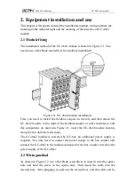
2.1 Module fixing
The installation method of the GC-4642 module is shown in Figure 2.1. You
need to use a flat-blade screwdriver for auxiliary installation.
Figure 2.1 GC-4642 module installation
First, you need to install the fieldbus coupler on the rail, and then attach the
GC-4642 module to the right of the fieldbus coupler or other modules to add
this component. As shown in Figure 2.1, insert the GC-4642 module inwards
along the slot until the latch snaps.
The GC-4642 module is powered by GC-bus, no additional power supply is
required. You only need to connect the power supply to the bus coupler and
connect the GC-4642 to the module composed of the bus coupler to realize the
power supply of the GC-4642.
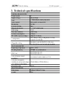
2.2 Wiringmethod
As shown in Figure 2.2, use a flat-blade screwdriver to insert it into the square
hole and hold the screw in the square hole. Then insert the cable into the
circular hole. After plugging in, pull out the screwdriver, and the cable can be