background image

 © 2004 General Binding Corporation

Spartan Operation and Maintenance  Manual

Page 4-1

4.0  Installation

GBC Films Group is committed to a program of ongoing
product improvement. As a result, we are providing these
instructions so that you can insure that your new Spartan
Laminator is properly and securely unpacked, moved and
installed.

Before a Spartan Laminator can be installed, there are a
few requirements that must be met. Make certain that
each of the requirements listed in the following pre-
installation checklist are met before beginning installation.

CAUTION: Failure to follow the pre-installation
check list can result in damage to the laminator.

4.1  Pre-installation

Are the doorways and hallways wide enough for
the laminator to be moved to the installation site?

Is there ample room for the laminator?

A work area must be established that allows for
unrestricted movement around the laminator and
provides space for efficient material flow. Figure
4.1.4 and Figure 4.1.5 illustrates a typical machine
area layout.

Is the environment appropriate for the laminator?

The laminator requires a clean, dust and vapor
free environment to operate properly. It must not
be located where there is air blowing directly on
the machine.

Have you contacted a certified electrician to install
a receptacle for the laminator ensuring that
adequate power is being supplied and correct
circuit breaker?

WARNING: The operating environment must be
free of dust, flammable liquids and vapors. You can
be injured by inhaling chemical vapors.

WARNING: Vapor build up or stored flammable
liquids can cause a fire. Excessive dust can damage
the laminator.

CAUTION: Do not locate the laminator where air
can blow directly on the machine. The air flow can
cool the rollers unevenly and result in poor quality
output.

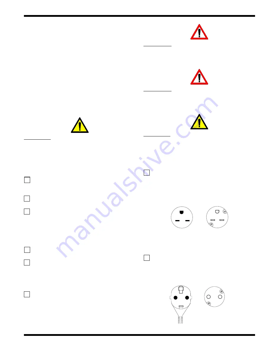
US and Canada: The laminator requires 230-

240 vac, 60 Hz, 15 amps, single phase

Figure 4.1.1 Connections-Spartan US

N E M A 6   -  1 5 R

N E M A 6   -  1 5 P

Europe: The laminator requires 230-240, 50 Hz
16 amps, single phase

Figure 4.1.2  Connections-Spartan Europe

1 6   re c e p ta c le

1 6   p lu g

Содержание 930-073

Страница 1: ...L 60062 4195 SPARTAN LAMINATOR OPERATION MAINTENANCE MANUAL 2004 GENERAL BINDING CORPORATION ALL RIGHTS RESERVED Do not duplicate without written permission REA DY U U S G S P R G E A L AMIN AT E O AM...

Страница 2: ...ducts described in it without notice All specifications and information concerning products are subject to change without notice Reference in this publication to information or products protected by c...

Страница 3: ...3 2Function 3 1 3 3 Electrical 3 1 3 4 Dimensions and weights 3 1 Figure 3 4 1 Dimensions 3 2 4 0 Installation 4 1 Pre installation 4 1 4 2 Suggested floor layout 4 2 Figure 4 2 1 Suggested floor layo...

Страница 4: ...2004 General Binding Corporation Spartan Operation and Maintenance Manual Page II...

Страница 5: ...ion following this symbol is to inform you of how to avoid a dangerous situation ELECTRICALHAZARD Thissymbolisusedprior to a step The information following this symbol is to prevent an electrical shoc...

Страница 6: ...stand a label consult your manager for assistance Electrical Shock Electrical shock hazard Electricalvoltagebehindpanel MUCHO CUIDADO Riesgo de choque electrico No abra Adentro no hay piezas reparable...

Страница 7: ...ING ATTENZIONE WARNUNG Electrical shock hazard Do not open No user serviceable parts inside Refer servicing to qualified service personnel Kans op elektrische schok Niet openen Bevatgeen door gebruik...

Страница 8: ...2004 General Binding Corporation Spartan Operation and Maintenance Manual Page 1 4...

Страница 9: ...authorized customer alterations will void this warranty THE WARRANTY MADE HEREIN IS IN LIEU OF ALL OTHER WARRANTIES EXPRESSED OR IMPLIED INCLUDING ANY WARRANTY OR MERCHANTABILITY OR FITNESS FOR A PART...

Страница 10: ...2004 General Binding Corporation Spartan Operation and Maintenance Manual Page 2 2 This page intentionally left blank...

Страница 11: ...Motor DC gear motor Heating Preset for GBC materials Controls Operationscontrolpanel Roll Design Highreleasesilicone 3 3 Electrical Laminator Rating 240V 60 Hz 2500 W Requirements 230 240 VAC 60 Hz s...

Страница 12: ...004 General Binding Corporation Spartan Operation and Maintenance Manual Page 3 2 Figure 3 4 1 Dimensions 42 in 105 cm RE ADY U U S G S P R G E A LAM IN AT E O AM PO UC H R E 53 in 132 cm 18 5 in 46 c...

Страница 13: ...flow Figure 4 1 4andFigure4 1 5illustratesatypicalmachine arealayout Istheenvironmentappropriateforthelaminator The laminator requires a clean dust and vapor freeenvironmenttooperateproperly Itmustnot...

Страница 14: ...with thematerialsathandwhilebeingfreetomovearoundthe laminatorwithoutinterferencefromthelaminator Refer tothefigurebelowforasuggestedfloorlayoutexample Figure 4 2 1 Suggest floor layout example 18ft 5...

Страница 15: ...H R E Rear Front Control side Drive side Parts on the laminator READY U U S G S P R G E A LAM IN AT E O AM PO U C H R E Cover Cabinet Table Stand Pouch rack Board rack Castors Under the cover R E A D...

Страница 16: ...tthemachineforanyobviousshipping damages upon receipt 2 Carefully unwrap the shrink wrap from around the laminator CAUTION Do not use a knife or other sharp object to remove any shrink wrap from aroun...

Страница 17: ...r runandmotorstopfunction Figure 5 1 1 Control panel READY SPARTAN GBC Run switch Stop switch Run indicator Ready indicator RUN When pressed engages the motor that drivestherollers INFORMATION The lam...

Страница 18: ...isrequired Thisisthemaximumnipopening position Foam pouch position Usethispositionwhenusingboardtypematerialsthrough the laminator This nip opening and speed is preset for GBCmaterials Laminatingposit...

Страница 19: ...empurature reach correct operating tempurature The top roll sensor only reads the top roll and the bottom roll may not be the correct tempurature 6 1 Pouch boards 1 Turnthelaminatoron 2 Center the ima...

Страница 20: ...to the foam pouch position 4 WaitforREADYtoilluminate 5 Press RUN 6 Aligntheleadingedgeofthemountingboardslightly off center of the table 7 Gentlyslidethemountingboardintotherollernipuntil you feel th...

Страница 21: ...over 4 Centertheimageonthelaminationpouchandcarefully lay the top sheets back over the image Pouch carrier Lamination pouch Image 5 Set the pressure handle to the lamination position 6 WaitforREADYtoi...

Страница 22: ...achine2 3times to help cool the bottom roller Laminating Pouches Toreducewavingaffect matchthesizeofthepouchas close to the image size as possible This will allow the stressesontheenvelopetobemoreeven...

Страница 23: ...ntain clean and adhesive free nip rollers and overall cleanlinessofthelaminatoritself ELECTRICAL HAZARD Do not use liquid or aerosol cleaners on the laminator Do not spill liquid of any kind on the la...

Страница 24: ...pick or pull heat activated adhesive off the rolls when they are cold You can cause irreparable damage to the laminating rolls CAUTION The following procedure is performed while the laminator is HOT U...

Страница 25: ......

Страница 26: ...General Binding Corporation One GBC Plaza Northbrook IL 60062 4195...

Отзывы: