F
M
M
oulded
splitt
er
+
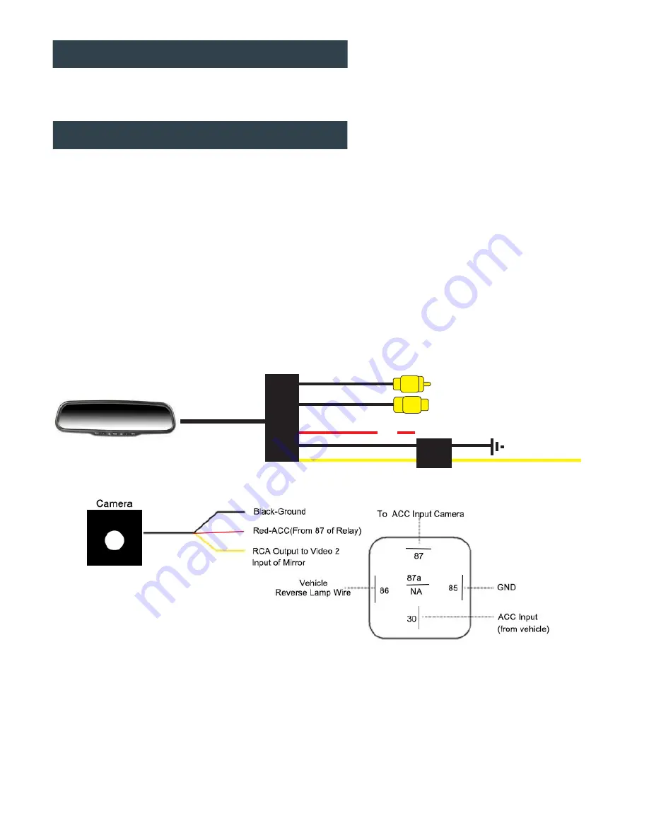
(Camera priority)
(Video1 input)
(Video2 input)
(Red-Accessory)
(Black- Ground)
(Yellow B+ to the fuse
of the car battery)
Inline
fuse
Installation Notes
This system is has signal sensing, there is no “reverse trigger wire” in the wire harness. Be sure to
use a
relay with CANBUS vehicles
(not included) to power your camera, as most vehicles’ reverse
lamp wires are now variable voltage wires, and will cause a fuzzy or distorted image. (PIC 2)
Installation
1. Remove OEM mirror and replace with supplied LCD mirror. LCD mirror can be mounted to the
vehicles existing window mounts, or by using the adapter and glass mounting metal button
included. Glue the mounting metal button to the vehicles window glass using rear view mirror
glue (not included). Tighten mount to metal button with Allen key provided.
2. Adapters for other vehicles can also be purchased separately. (www.aerpro.com.au)
3. Run your wiring harness into the headliner and down the vehicles A-Pillar, making sure to
avoid any factory airbags. Secure your wiring with zip-ties.
4. Make all necessary wiring connections (See wiring diagram PIC 1)
PIC 1
PIC 2
Black (Ground)
– Locate a suitable location to ground (negative) the Black wire in the wiring
harness. You may connect this wire to a factory ground point in the vehicle, or attach a ring terminal
to the black wire and screw into the body of the vehicle. If you choose to screw into the body, clean
the area of any paint or adhesives to allow for good metal-to-metal contact.
Содержание GR430EDR
Страница 1: ...USER GUIDE GR430EDR...
Страница 12: ......


