background image

Instructions for DKC500DCL/DKC800DCL

www.gatexpertstore.com

17

7

Auto-reverse Function

ON–enable
OFF–disable
Default position is ON, this should align with the
opener status and is not recommended to be
modified by the users.

8

Photocell Delay
Detection

ON–enable
OFF–disable
Please enable this function if your motor is
connected with a photocell

Potentiometer Adjustment

All changes to these settings must be completed by a licensed electrician

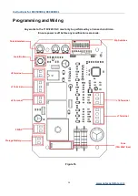
Figure 18

VR1: Motor Total Working Time Adjustment

Total working time is the maximum running time of the motor after user makes operation on
it, for example, to open and close your gate requires 20 seconds and you set the total
working time in 20 seconds, due to some interruptions, the gate doesn’t finish the travel
within 20 seconds, it’ll anyway stopped after 20 seconds.
Clockwise to increase the time, counter-clockwise to reduce. Time can be adjusted from 10
seconds to 90 seconds. We recommend to add 5 seconds on the actual running time. E.g.
gate running requires 20 seconds, then set this total working time to be 25 seconds.

VR2: Without Functions

VR3: Motor Auto-reverse Force Adjustment

This VR3 is for adjusting the Auto-reverse force when meeting obstacles, clockwise to
increase the force, counter-clockwise to reduce.

Содержание DKC500DCL

Страница 1: ...Sliding Gate Opener User Manual DKC500DCL DKC800DCL Website www gatexpertstore com E mail sales gatexpertstore com...

Страница 2: ...operation When mounting and positioning this product please ensure the power cable is unplugged The motor cover will need to be removed to mount the motor to the mounting plate or directly to the con...

Страница 3: ...e or replace for free 4 The malfunction and damages caused by incorrect use or man fault is not covered by this warranty CONTACT US E mail sales gatexpertstore com Please fill in the order information...

Страница 4: ...otor Pad Footing 8 Step 5 Fitting Mounting Base and Motor 8 Step 6 Sprocket and Chain Motor Alignment 10 Step 7 Limit Switch Stops 11 Step 8 Powering on 13 Step 9 Testing Travel and Limit Stops 14 Pro...

Страница 5: ...to the opposite direction This will give you an understanding of the way how the opener moves the gate Figure 2 Note Ensure that the gate opener is unplugged before proceeding with installation Pleas...

Страница 6: ...event injury to person or damage to property Instruct all users about the control systems provided and the manual opening operation in case of emergency Ensure that the power cable is connected to a R...

Страница 7: ...No Picture Name Quantity 1 Motor 1 2 Manual Release Keys 2 3 Remote Controls 2 4 Mounting Accessories Box 1 4 1 Sprocket Cover 1 4 2 Chain Including 2 Chain Links 6m 4 3 Tie Rod 2 4 4 Square Screw 4 4...

Страница 8: ...t M8 4 Flat Washer 8 2 Spring Washers 8 2 4 11 Inner Hexagon Head Bolt M6X20 4 4 12 Hexagon Head Bolt M8X40 4 4 13 Nut M6 16 Nut M8 16 4 14 Flat Washer 6 16 Flat Washer 8 16 4 15 Spring Washers 6 16 S...

Страница 9: ...switch Working Noise 58dB Working Duty S2 20min Recording of up Remote Controls 40 Remote Frequency 433 92 MHz Working Temperature 20 C 70 C Package Weight 16 42KG 16 5KG Installation Before You Star...

Страница 10: ...s not plugged in at any stage before Step 8 Step 1 Gate Preparation Ensure that the sliding gate is correctly installed The gate is horizontal and level and the gate can glide back and forth smoothly...

Страница 11: ...e 6 Figure 6 Step 3 Removing Installing Motor Cover Unscrew the two cover screws located at each side of the motor cover Remove the rubber grommet below the limit switch Figure 7 Figure 7 Sprocket cov...

Страница 12: ...long x 350mm wide and a minimum depth of 200mm Standard requirement Ensure surface is level and parallel to the driveway Mounting Base Dimensions Figure 9 Step 5 Fitting Mounting Base and Motor Fit a...

Страница 13: ...tput sprocket and chain are correctly aligned Sprocket and chain should be centered as much as possible Take the motor away from mounting base Leave a space of 30cm from the motor to end of the chain...

Страница 14: ...rcumstances should the gate opener output sprocket carry any weight of the gate It is the task of the gate castors or wheels to carry the weight of the gate If the gate doesn t slide freely by hand ad...

Страница 15: ...g It is extremely dangerous that without or incorrect installation of the limit switch stops can cause crash of gate damage of internal structure of the motor moreover the gate may slide off the guide...

Страница 16: ...when setting the open position under power Fit limit switch stop onto the top of chain at the point where it meets the magnetic limit switch on the motor Tighten locking screws of limit switch stop T...

Страница 17: ...r has been fitted and fastened back onto the motor base Before powering up the gate opener make sure the gate can travel by hand in manual mode key unlocked Slide the gate to between the middle of the...

Страница 18: ...te frame is 10 15mm from closed gate end catch Testing the Open Position Press remote the sliding gate will begin to open The limit switch stop will hit the limit switch and the sliding gate will stop...

Страница 19: ...l Dip Switches Learn Button Potentiometers Storage Battery Programming and Wiring Any works to the 110V 220V AC must only be performed by a licensed electrician Ensure power is off before any modifica...

Страница 20: ...30s 1 OFF 2 OFF no automatic close function Default setting 1 OFF 2 OFF Disable the automatic close function 2 3 Remote Control Mode Switch ON three button mode first button open second button close...

Страница 21: ...nning time of the motor after user makes operation on it for example to open and close your gate requires 20 seconds and you set the total working time in 20 seconds due to some interruptions the gate...

Страница 22: ...ed to be swapped but also the wires of OP and CL on J10 Terminal have to be swapped with each other J8 Terminal as per Figure 16 Terminal ALM Alarm Lamp 24VDC Terminal ALM Alarm Lamp 24VDC J1 Terminal...

Страница 23: ...ace J10 Terminal OP Open Limit Switch COM Limit Switch Common Terminal CL Close Limit Switch J7 Terminal External Push Button Terminal 1 External Open Push Button Switch N O Terminal 2 External Close...

Страница 24: ...rician Highly recommend the use of infrared photocells as an additional safety feature While closing if the ray of the Infrared Photocell is blocked the gate will stop and reverse immediately to prote...

Страница 25: ...Mode Remote Control Figure 21 Remote Control Learning Remove motor outer cover and continue to remove the transparent PCB cover press the button K4 on the control board until the LEARN indicator light...

Страница 26: ...D6 DKC500DC PCB DKC500DC PCB 2015 01 05 2015 01 05 R8 R8 R9 R9 C23 C23 POWER POWER Solar Solar panel panel Solar Solar charger charger Storage Storage battery battery Control Control board board Figur...

Страница 27: ...AC 220VAC Transformer Transformer output output 24VAC 24VAC Figure 24 Maintenance The gate should be checked every month to make sure it operates normally For the sake of safety each gate is suggested...

Страница 28: ...e photocell mounting position can be mutually aligned 3 Remove the obstacle 4 Increase the sensitivity of obstacle Remote control doesn t work 1 Battery level is too low 2 Remote control not paired 1...

Страница 29: ...Instructions for DKC500DCL DKC800DCL www gatexpertstore com 25 Drawing and Measurements Figure 25...

Отзывы: