CHAPTER 3: Replacing notebook components
112
6
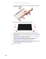
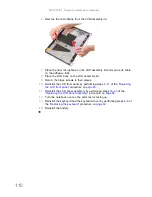
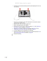
Carefully pry the antenna boards loose from the LCD assembly lid to remove
the antennas.
7
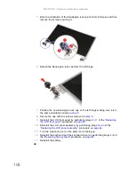
Secure the new antenna on the LCD assembly lid and route their cables
underneath the adhesive tabs.
8
Place the LCD back on the LCD assembly lid.
9
Return the hinge screws to their places.
10
Reinstall the LCD front panel by performing steps
8
–
11
of the
“Replacing
the LCD front panel”
procedure on
page 95
.
11
Reinstall the LCD panel assembly by performing steps
16
–
23
of the
“Replacing the LCD panel assembly”
procedure on
page 64
.
12
Turn the notebook over so the palm rest is facing up.
13
Reinstall the keyboard and the keyboard cover by performing steps
5
–
8
of
the
“Replacing the keyboard”
procedure on
page 62
.
14
Reinstall the battery.
Содержание NV55
Страница 1: ... NV55 SERVICEGUIDE ...
Страница 6: ...Contents iv ...
Страница 12: ...CHAPTER 1 System specifications 6 System block diagram ...
Страница 48: ...CHAPTER 2 System utilities 42 ...
Страница 140: ...CHAPTER 4 Troubleshooting 134 ...
Страница 141: ...CHAPTER5 135 Connector locations System board layout ...
Страница 145: ...CHAPTER6 139 FRU Field Replaceable Unit list Introduction Exploded diagram FRU list ...
Страница 152: ...CHAPTER 6 FRU Field Replaceable Unit list 146 ...
Страница 153: ...APPENDIXA 147 Test compatible components Introduction Microsoft Windows 7 Compatibility Test ...
Страница 156: ...APPENDIX A Test compatible components 150 ...
Страница 157: ...APPENDIXB 151 Online support information ...
Страница 163: ......
Страница 164: ...MAN NV5x SVC GDE R1 04 09 ...


