CHAPTER 4: Upgrading Your Computer
44
5
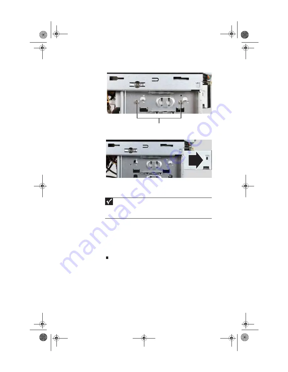
Remove the two drive retention screws.
6
Slide the drive forward and out of the drive bay.
7
Slide the new drive into the drive bay, line up the screw
holes on the drive bay with the screw holes on the drive,
then replace the two drive retention screws.
8
Reconnect the drive cables using your notes from
Step 3
,
or according to the manufacturer’s instructions.
9
Replace the front bezel by following the instructions in
“Replacing the front bezel” on page 38
10
Replace the side panels by following the instructions in
“Replacing the side panels” on page 39
Important
Make sure that the optical drive’s screw holes are lined up with the
correct holes in the drive bay. If the drive screws are mounted through
the wrong holes, the front of the drive will protrude too far out the front
of the case for the front bezel to be reinstalled.
Drive retention screws
8513027.book Page 44 Friday, April 25, 2008 5:27 PM
Содержание GT5694
Страница 1: ...REFERENCEGUIDE 8513027 book Page a Friday April 25 2008 5 27 PM...
Страница 2: ...8513027 book Page b Friday April 25 2008 5 27 PM...
Страница 10: ...CHAPTER 1 About This Reference 4 8513027 book Page 4 Friday April 25 2008 5 27 PM...
Страница 11: ...CHAPTER2 5 Checking Out Your Computer Front Back 8513027 book Page 5 Friday April 25 2008 5 27 PM...
Страница 38: ...CHAPTER 3 Setting Up and Getting Started 32 8513027 book Page 32 Friday April 25 2008 5 27 PM...
Страница 56: ...CHAPTER 4 Upgrading Your Computer 50 8513027 book Page 50 Friday April 25 2008 5 27 PM...
Страница 74: ...CHAPTER 5 Maintaining Your Computer 68 8513027 book Page 68 Friday April 25 2008 5 27 PM...
Страница 106: ...CHAPTER 6 Troubleshooting 100 8513027 book Page 100 Friday April 25 2008 5 27 PM...
Страница 116: ...APPENDIX A Legal Notices 110 8513027 book Page 110 Friday April 25 2008 5 27 PM...
Страница 125: ...8513027 book Page 119 Friday April 25 2008 5 27 PM...
Страница 126: ...MAN GERSHWIN3 GWREC REF GDE R0 4 08 8513027 Back fm Page 120 Monday April 28 2008 8 13 AM...


