


22
Chapter 2
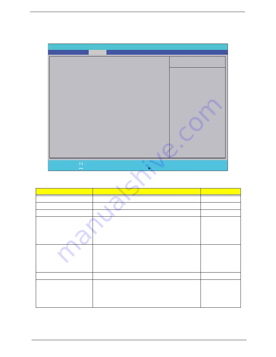
Security
The Security screen contains parameters that help safeguard and protect your computer from unauthorized
use.
The table below describes the parameters in this screen. Settings in
boldface
are the default and suggested
parameter settings.
NOTE:
When you are prompted to enter a password, you have three tries before the system halts. Don’t forget
your password. If you forget your password, you may have to return your notebook computer to your
dealer to reset it.
Parameter
Description
Option
Supervisor Password Is
Shows the setting of the Supervisor password
Clear
or Set
User Password Is
Shows the setting of the user password.
Clear
or Set
IDEO HDD Password Is
Shows the setting of the HDD password
Clear
or Set
Set Supervisor Password
Press Enter to set the supervisor password. When
set, this password protects the BIOS Setup Utility
from unauthorized access. The user can not either
enter the Setup menu nor change the value of
parameters.
Set User Password
Press Enter to set the user password. When user
password is set, this password protects the BIOS
Setup Utility from unauthorized access. The user can
enter Setup menu only and does not have right to
change the value of parameters.
Set IDEO Hdd Password
Enter to set the HDD password.
Power on password
Defines whether a password is required or not while
the events defined in this group happened. The
following sub-options are all requires the Supervisor
password for changes and should be grayed out if the
user password was used to enter setup.
Enabled or
Disabled
I t e m S p e c i f i c H e l p
S u p e r v i s o r P a s s w o r d c o n t r o l s
a c c e s s t o t h e w h o l e s e t u p
u t i l i t y. I t c a n b e u s e d t o b o o t
u p w h e n P a s s w o r d o n b o o t i s
e n a b l e d .
F 1
E S C
H e l p
E x i t
S e l e c t I t e m
S e l e c t M e n u
C h a n g e Va l u e s
S e l e c t
S u b M e n u
E n t e r
F 9
F 1 0
S e t u p D e f a u l t
S a v e a n d E x i t
C l e a r
C l e a r
C l e a r
C l e a r
[ D i s a b l e d ]
S u p e r v i s o r P a s s w o r d I s :
U s e r P a s s w o r d I s :
S e t S u p e r v i s o r P a s s w o r d
S e t U s e r P a s s w o r d
S e t I D E 0 H d d P a s s w o r d
S u p e r v i s o r P a s s w o r d I s :
U s e r P a s s w o r d I s :
I D E 0 H D D P a s s w o r d I s : F r o z e n
S e t S u p e r v i s o r P a s s w o r d
S e t U s e r P a s s w o r d
S e t I D E 0 H d d P a s s w o r d
P o w e r o n p a s s w o r d
F 5 / F 6
I n s y d e H 2 0 S e t u p U t i l i t y R e v. 3 . 0
Information
Main
Boot
Exit
Security
Содержание EC14D
Страница 6: ...VI ...
Страница 10: ...X Table of Contents ...
Страница 45: ...Chapter 2 35 ...
Страница 46: ...36 Chapter 2 ...
Страница 81: ...Chapter 3 71 5 Lift out entire speaker module ...
Страница 104: ...94 Chapter 3 3 Replace the one 1 screw 4 Replace the FFC and adhere the adhesive tape over the cable ...
Страница 108: ...98 Chapter 3 5 Connect the thermal module cable to the mainboard ...
Страница 111: ...Chapter 3 101 7 Replace the CRT cable 8 Connect the speaker and card reader board cables ...
Страница 117: ...Chapter 3 107 Replacing the LED Board 1 Replace the LED board 2 Replace the one 1 screw 3 Connect the LED board FFC ...
Страница 119: ...Chapter 3 109 3 Beginning with the bottom edge press around the edges of the upper cover to snap it into place ...
Страница 124: ...114 Chapter 3 3 Gently slide the ODD back into the chassis 4 Replace the one 1 screw to secure the ODD module in place ...
Страница 150: ...140 Chapter 4 ...
Страница 156: ...146 Chapter 5 ...
Страница 169: ...Chapter 6 159 ...
Страница 178: ...168 Appendix C ...
Страница 182: ...172 ...


