Chapter 2
21
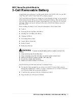
Main
The Main screen allows the user to set the system time and date as well as enable and disable boot option
and recovery.
NOTE:
The screen above is for your reference only. Actual values may differ.
The table below describes the parameters in this screen. Settings in
boldface
are the default and suggested
parameter settings.
Parameter
Description
Format/Option
System Time
Sets the system time. The hours are displayed with 24-
hour format.
Format: HH:MM:SS
(hour:minute:second)
System Date
Sets the system date.
Format MM/DD/YYYY
(month/day/year)
Total Memory
This field reports the memory size of the system.
Memory size is fixed to 3017 MB.
N/A
Video Memory
Shows the video memory size. VGA Memory size=32 MB
N/A
Quick Boot
Allows startup to skip certain tests while booting,
decreasing the time needed to boot the system.
Option:
Enabled
or Disabled
Network Boot
Enables, disables the system boot from LAN (remote
server).
Option:
Enabled
or Disabled
F12 Boot Menu
Enables, disables Boot Menu during POST.
Option:
Enabled
or Disabled
D2D Recovery
Enables, disables D2D Recovery function. The function
allows the user to create a hidden partition on hard disc
drive to store operation system and restore the system
to factory defaults.
Option:
Enabled
or Disabled
SATA Mode
Control the mode in which the SATA controller should
operate.
Option:
AHCI
or IDE
I t e m S p e c i f i c H e l p
< Ta b > , < S h i f t - Ta b > , o r
< E n t e r > s e l e c t s f i e l d
F 1
E S C
H e l p
E x i t
S e l e c t I t e m
S e l e c t M e n u
C h a n g e Va l u e s
S e l e c t
S u b M e n u
E n t e r
F 9
F 1 0
S e t u p D e f a u l t
S a v e a n d E x i t
[ 1 3 : 5 5 : 5 9 ]
[ 0 4 / 0 9 / 2 0 0 9 ]
1 0 2 4 M B
[ E n a b l e d ]
[ E n a b l e d ]
[ E n a b l e d ]
[ E n a b l e d ]
[ A H C I M o d e ]
[ 1 3 :
5 5 : 5 9 ]
[ 0 4 / 0 9 / 2 0 0 9 ]
1 0 2 4 M B
[ 6 4 M B ]
[ E n a b l e d ]
[ E n a b l e d ]
[ E n a b l e d ]
[ E n a b l e d ]
[ A H C I M o d e ]
S y s t e m Ti m e :
S y s t e m D a t e :
To t a l M e m o r y :
Vi d e o M e m o r y :
Q u i c k B o o t
N e t w o r k B o o t
F 1 2 B o o t M e n u
D 2 D R e c o v e r y
S ATA M o d e
S
y s t e m Ti m e :
S y s t e m D a t e :
To t a l M e m o r y :
Vi d e o M e m o r y :
Q u i c k B o o t
N e t w o r k B o o t
F 1 2 B o o t M e n u
D 2 D R e c o v e r y
S ATA M o d e
F 5 / F 6
I n s y d e H 2 0 S e t u p U t i l i t y R e v. 3 . 0
Boot
Exit
Security
Information
Main
Содержание EC14D
Страница 6: ...VI ...
Страница 10: ...X Table of Contents ...
Страница 45: ...Chapter 2 35 ...
Страница 46: ...36 Chapter 2 ...
Страница 81: ...Chapter 3 71 5 Lift out entire speaker module ...
Страница 104: ...94 Chapter 3 3 Replace the one 1 screw 4 Replace the FFC and adhere the adhesive tape over the cable ...
Страница 108: ...98 Chapter 3 5 Connect the thermal module cable to the mainboard ...
Страница 111: ...Chapter 3 101 7 Replace the CRT cable 8 Connect the speaker and card reader board cables ...
Страница 117: ...Chapter 3 107 Replacing the LED Board 1 Replace the LED board 2 Replace the one 1 screw 3 Connect the LED board FFC ...
Страница 119: ...Chapter 3 109 3 Beginning with the bottom edge press around the edges of the upper cover to snap it into place ...
Страница 124: ...114 Chapter 3 3 Gently slide the ODD back into the chassis 4 Replace the one 1 screw to secure the ODD module in place ...
Страница 150: ...140 Chapter 4 ...
Страница 156: ...146 Chapter 5 ...
Страница 169: ...Chapter 6 159 ...
Страница 178: ...168 Appendix C ...
Страница 182: ...172 ...