


Intraplex
®
IP Link 100e
Quick Start Guide v1.0
Page
6
of
8
4. Click
OK
to reset the system and
load the IP Link 100e Software.
Figure 13. Firmware Manager
F)
Configure the Network Interfaces
1. Type the
Username
and
Password
of the Engineer account you just
created.
2. Click
Log in
. The IP Link 100e
home page appears (
Figure 14
).
Figure 14. Home Page
3. On the IP Link 100e home page, click
Network Interfaces
on the
Network
tab. The
Networking
page appears
(
Figure 15
).
Figure 15. Networking Settings
4. Click on the active network interface
to bring up its settings.
5. Either enable
DHCP
or disable
DHCP to set a static
IP Address
and
Subnet Mask
for the connected
network.
6. Click
Apply
.
7. Enter the newly applied IP address
into the browser’s address bar (as in
Section B, Step 2
) and press enter.
Note
: If the system is assigned a
new network address, you may also
need to reconfigure your PC to
regain access.
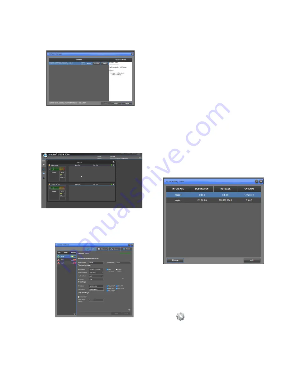
G)
Define a Static Route
If you are using IP Link 100e on a
different subnet, perform these steps to
define a static route:
1. Under the
Networking
tab, click the
Forwarding Table
. The
Forwarding Table
page appears
(
Figure 16
).
Figure 16. Forwarding Table
2. Configure the
Destination
,
Netmask
, and
Gateway
.
3. Click
Apply
.
H)
Configure Channels
To configure the channel settings, click
the
on the top right of the channel.
This will show the
Channel
page
(
Figure 17
). Here you will find tabs for


