background image

Intelligent Temperature Sensing Systems(ITSS)            

Pedestal Mount Installation Manual 


Page 

6

 of 

8


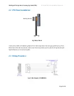
There are only 3 wires that need to be connected. The 12VDC, GND and IGN. All other wires are for 
future use only. Connect these three wires to the bus, then plug the connector into the Temperature 
Panel. Use cable ties to hide excess cables and unused wires. 

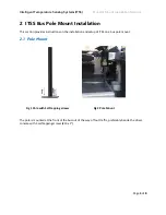
The monitor comes pre configured.  Make sure the panel is correctly facing the stairs and is angled down 
slightly. 

Refer to ITSS user guide or reach to our technical support for any further information you may require.  


2.4


Installation Requirements 

As part of installation best practices, it is recommended to mount the device in the vehicle cabin area 
where there is environmental control (i.e. heating and/or air-conditioning). This will extend the device 
operating life by not exposing it unnecessarily to adverse environmental conditions.  

Refer to the manual for any further information you may require. 


The device has an operating temperature range of 0°C - 50°C (32°F to 122°F). Please ensure 
that the device is mounted in an area in which acceptable temperature ranges are 
experienced. 


To ensure the Customer Warranty is not voided do not disassemble the unit and refer to 
wiring diagram for correct connections.  


Содержание ITSS

Страница 1: ...ture Sensing Systems ITSS Pedestal Mount Installation Manual Page 1 of 8 Intelligent Temperature Sensing System Bus Pole Mount Installation Guide Kkkkkk Document Ref No DN3320 Version No 1 0 1 Documen...

Страница 2: ...TABLE OF CONTENTS 1 INTRODUCTION 3 1 1 WELCOME TO YOUR NEW INTELLIGENT TEMPERATURE SENSING SYSTEM 3 2 ITSS BUS POLE MOUNT INSTALLATION 4 2 1 POLE MOUNT 4 2 2 ITSS PANEL INSTALLATION 5 2 3 WIRING PROCE...

Страница 3: ...that detects temperatures of passengers in a transportation environment Artificial Intelligence is used to detect the presence of a face A thermal sensor is used to calculate the individual s tempera...

Страница 4: ...tallation This section provides instructions on the installation and setup of ITSS on a bus pole mount 2 1 Pole Mount Fig 1 Pole with Self tapping screws Fig 2 Pole Mount The pole is mounted at the fr...

Страница 5: ...cking bracket Fig 4 Panel Mount Unscrew the 4 bolts on the Backing bracket from the Temperature Panel using supplied hex key Place Panel mount brackets around pole and reinsert the screws Make sure th...

Страница 6: ...further information you may require 2 4 Installation Requirements As part of installation best practices it is recommended to mount the device in the vehicle cabin area where there is environmental c...

Страница 7: ...odified so as to adversely affect the products operation performance or durability or that has been altered or modified so as to change its intended use Gatekeeper Systems Inc is not responsible for l...

Страница 8: ...e 1 888 666 4833 GATEKEEPER SYSTEMS USA INC 7 200 Rittenhouse Circle Bristol PA 19007 Tel 1 604 864 6187 Fax 1 604 864 8490 Toll Free 1 888 666 4833 SALES TECHNICAL SUPPORT For technical support conta...

Отзывы: