background image

www.gastron.com

18

_

19

GTC-540

Instruction Manual

6.4. Operation Setting

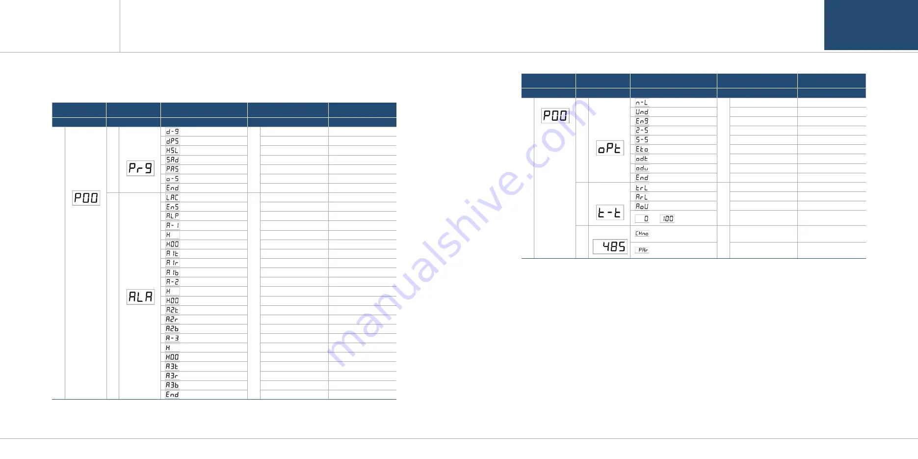
6.4.1. Setting Table

LEVEL1

LEVEL2

LEVEL3

LEVEL4

(Range available for Selection)

DEFAULT

FUNC→

FUNC→

FUNC →

FUNC → NEXT

U

P

&
D
O

W

N

P

A

S
S

W

O

R

D

I

N

P

U

T

U

P

&
D
O

W

N

  (Gas Funtion)

U

P

&
D
O

W

N

TY1, Ty2, TY3, TY4

TY1

  (Decimal-Point)

100, 10.0, 1.00

100

  (High-Scale)

10~999

100


-99 ~ 99

0

  (Pass Word)

0~99

00

  (Out-Set)

ON, OFF

OFF

  (End)

-

-

U

P

&
D
O

W

N

  (LACH)

U

P

&
D
O

W

N

ON, OFF

ON

  (Energizer)

ON, OFF

OFF

  (Alarm Lamp)

ON, OFF

OFF

  (Alarm-1)

1~Full range

20%/F.R.

  (1H)

H, L

H

  (1H 00)

0~99

00

  (Alarm 1 Time Delay)

0~60

0

  (Alarm 1 Relay)

ON, OFF

ON

  (Alarm 1 Blink)

ON, OFF

OFF

  (Alarm-2)

1~Full range

40%/F.R.

  (2H)

H, L

H

  (2H 00)

0~99

00

  (Alarm 2 Time Delay)

0~60

0

  (Alarm 2 Relay)

ON, OFF

ON

  (Alarm 2 Blink)

ON, OFF

OFF

  (Alarm-3)

1~Full range

50%/F.R.

  (3H)

H, L

H

  (3H 00)

0~99

00

  (Alarm 3 Time Delay)

0~60

0

  (Alarm 3 Relay)

ON, OFF

ON

  (Alarm 3 Blink)

ON, OFF

OFF

  (End)

-

-

[Table 4. Setting Table]

PROGRAM

MODE

ALARM

MODE

LEVEL1

LEVEL2

LEVEL3

LEVEL4

(Range available for Selection)

DEFAULT

FUNC→

FUNC→

FUNC →

FUNC → NEXT

U

P

&
D
O

W

N

P

A

S
S

W

O

R

D

I

N

P

U

T

U

P

&
D
O

W

N

 (Maintenance-Level)

U

P

&
D
O

W

N

0 ~ Full range

0

 (Under)

ON / OFF

ON

 (Engineering)

ON / OFF

OFF

 (Zero-Skip)

0 ~ 20.0%

0

 (Span-Skip)

0 ~ 20.0%

0

 (Emergency-Timeout)

ON / OFF

OFF

 (Output Delay Time)

0 ~ 60sec

5

 (Output Delay Value)

0 ~ 20%

7

 (End)

-

-

U

P

&

D

O

W

N

 (Trouble Relay)

U

P

&

D

O

W

N

ON / OFF

OFF

 (Alarm Relay)

ON / OFF

OFF

 (mA out)

ON / OFF

OFF

 or            (0 or 100)

0 or 100 (Flickering)

When ON, starts from 100
When OFF, starts from 

U

P

&

D

O

W

N

 (Channel number)

U

P

&

D

O

W

N

0~128

1

 (Parity Bit)

0~2

1

OPTION

MODE

485 MODE

TEST

MODE

6. Operation Method

6. Operation Method

Содержание GTC-500 Series

Страница 1: ...nce d Industry 1 ro Bugok dong Gunpo si Gyeonggi do Tel 82 31 490 0800 Fax 82 31 490 0801 Yeongnam business office Plant 55 Gonghangap gil 85beon gil Gangseogu Busan Metropolitan City Tel 51 973 8518 Fax 51 973 8519 E mail info gastron com www gastron com Read in detail for correct use ...

Страница 2: ...rmed quarterly when the calibration period is not specified In case of a problem after purchasing the product please contact the address below Address 23 Gunpo Advanced Industry 1 ro Gunpo si Gyeonggi do Tel 031 490 0800 Fax 031 490 0801 URL www gastron com e mail info gastron com The product and manual are subject to change without a notice for the product s functional improvement and ease of use...

Страница 3: ...l Specifications Standard Type 8 3 4 Environmental Specifications 8 4 Name and description of each part 10 5 Installation 10 5 1 Power Configuration 10 5 2 Signal Terminal Configuration 11 5 3 Relay Terminal Configuration 14 5 4 3 wire Type Gas detector Connection Method 15 5 5 2 wire Type Gas detector Connection Method 15 6 Operation Method 16 6 1 Power ON 16 6 2 Test Mode 17 6 3 Stand by Mode 17...

Страница 4: ...ince it has an output for an error SPDT contact GTC 540 receiver provides 4 20mA DC output for the measured value and is able to communicate digitally using RS 485 network signal Option 3 1 Basic Specifications ITEMS SPECIFICATION Measuring Value Display 1 8 3 Digit FND Bar graph 32 segment 3Color Measuring Range Capable to display 00 0 999 Alarm Indicator Visible Indicator 3 Alarm Trouble LED War...

Страница 5: ... 0 2mA Measured value signal 4mA Zero to 20mA Full Scale Fault 0 100 LEL 100 109 LEL Over 110 LEL Maintenance 0mA 4mA 20mA 21 6mA 20mA 21 4mA 3mA Analog output current ripple noise max 20uA Relay contact Alarm1 Alarm2 Alarm3 Fault Relay AC250V 5A Relay contact SPDT Wiring requirement Power CVVS or CVVSB with shield Analog CVVS or CVVSB with shield RS485 STP Shielded Twisted Pair Cable Connection L...

Страница 6: ...e the set value or to select the next setting When a value needs to be changes in a large range pressing UP S W for a certain time changes the value rapidly 16 DOWN S W After selecting each mode using FUNC S W use to decrease the set value or to select the previous setting When a value needs to be changes in a large range pressing DOWN S W for a certain time changes the value rapidly 17 TEST S W P...

Страница 7: ...r terminal block that connects power and various signals within PCB appears Connect AC Power 85 260 V 50 60 Hz to CN9 as shown in the figure below Figure 3 CN6 Terminal Configuration 5 2 Signal Terminal Configuration Using CN6 terminal connect 4 20 mA output External Reset RS485 and external gas detector Terminal configuration is as shown in the table below RS 485 cable uses a cable designated for...

Страница 8: ...Power DC 24 V Output 14 External Power DC 24 V Output Table 3 CN5 Terminal Description Figure 4 CN5 Terminal Configuration 5 4 3 wire Type Gas detector Connection Method 5 5 2 wire type Gas detector Connection Method Figure 5 3 wire type gas detector Figure 6 2 wire type gas detector When the gas detector has 3 wire V mA V for power and 420 mA output components connect to the Channel Unit as shown...

Страница 9: ...entration is detected to be above the set value for alarm alarm function counts the dwell time and if it is above the set dwell time alarm function operates Alarm relay turns on when it is above the alarm dwell time When Alarm Latch Type is at ON mode and alarm function runs the alarm status and gas concentration value stays at the maximum value When gas concentration decreases below the alarm val...

Страница 10: ...m 2 Relay ON OFF ON Alarm 2 Blink ON OFF OFF Alarm 3 1 Full range 50 F R 3H H L H 3H 00 0 99 00 Alarm 3 Time Delay 0 60 0 Alarm 3 Relay ON OFF ON Alarm 3 Blink ON OFF OFF End Table 4 Setting Table PROGRAM MODE ALARM MODE LEVEL1 LEVEL2 LEVEL3 LEVEL4 Range available for Selection DEFAULT FUNC FUNC FUNC FUNC NEXT U P D O W N P A S S W O R D I N P U T U P D O W N Maintenance Level U P D O W N 0 Full r...

Страница 11: ...ogram setting function when it passes 10 s after the last S W control it automatically returns to gas concentration display mode When FUNC S W is pressed it enters Program Mode When RESET S W is pressed it returns to gas concentration display mode It is gas selection function that cen be selected by gas type When FUNC S W is pressed it enters Gas Selection Mode When RESET S W is pressed it enters ...

Страница 12: ...changes when UP or DOWN S W are pressed When ON the actual gas mA value is displayed in any mode entered When OFF mA corresponding to each mode is outputted as the same as existing setting When a desired out set mode is displayed press FUNC S W to set it and enter the next item When RETURN S W is pressed it returns to Program Mode 6 4 3 ALARM Mode After setting a password move to UP S W or DOWN S ...

Страница 13: ...next item When RESET S W is pressed it returns to Alarm Setting Mode Default Alarm1 20 F S 20 Alarm2 40 F S 40 Alarm3 50 F S 50 Alarm level is set to the concentration outlined in domestic regulations as factory setting It is a mode to set a direction of Alarm 1 operation Pressing UP S W or DOWN S W displays H or L respectively H mode operates when gas value is equal or greater than Alarm1 setting...

Страница 14: ... Alarm 1 blink output does not run In ON mode it runs However it runs when Alarm1 contact output mode is ON When a desired Alarm 1 blink output mode is displayed press FUNC S W to set it and enter the next item When RESET S W is pressed it returns to Alarm Setting Mode A message indicating completion of setting is displayed as End for 2 sec then it returns to gas concentration display status Alarm...

Страница 15: ...ing is displayed as End for 2 sec then it returns to gas concentration display status 6 4 5 Test Mode After setting a password move to UP S W or DOWN S W then press FUNC S W to enter the mode In test mode when it passes 10 sec after the last S W control it automatically returns to gas concentration display mode Test mode enables testing without injecting gas to the detector sensor The user can set...

Страница 16: ...essed it enters Option setting mode When RESET S W is pressed it returns to gas concentration display mode It is channel Number Setting Function that sets Serial Number of Control Unit Press FUNC S W to enter Channel number setting function When RESET S W is pressed it returns to gas concentration display mode Full Range Channel number is a mode that enters serial number of control unit to enable ...

Страница 17: ...SET and TEST S W for 2 sec or longer in gas concentration display mode enters Maintenance mode RESET S W must be pressed in Maintenance mode to return to gas concentration display mode Mode that selects function to set current input and output values that are reference of Channel unit Pressing UP S W or DOWN S W displays In or oUt respectively When a desired mode is displayed press FUNC S W to set...

Страница 18: ...5 GTC 540 Instruction Manual It is a mode that tests output current after calibration Default 4 0 It can confirm a range for 3 0 mA 21 0 mA with UP S W and DOWN S W Pressing FUNC S W after confirmation goes to the next item When RESET S W is pressed it returns to gas concentration display mode A message indicating completion of setting is displayed as End for 2 sec then it returns to gas concentra...

Страница 19: ...High Scale Setting 30002 BIT15 0 High Scale Setting Integer Decimal point is not considered Alarm 1 Setting 30003 BIT15 0 Alarm 1 Setting Integer Decimal point is not considered Alarm 2 Setting 30004 BIT15 0 Alarm 2 Setting Integer Decimal point is not considered Gas detector status value 10000 BIT0 Alarm 1 Active Status BIT1 Alarm 2 Active Status BIT2 Alarm 3 Active Status BIT3 Fault Active Statu...

Страница 20: ...gure 8 GTC 540 Drawing 2 VERSION CONTENTS DATE 0 0 Initial Revision of Manual 2011 08 25 1 0 Changed Main PCB Layout and Added function 2014 01 15 2 0 Corrected Program Mode Function 2015 04 27 3 0 Changed Font 2016 09 23 9 Revision History 8 Drawings and Dimensions ...

Отзывы: