


G-Shield Instruction Manual
Version 1
13
Label
Connection Description
VOUT+ Positive supply voltage to Sensor Platform
A+
Signal A
B-
Signal B
GND
GND supply voltage to Sensor Platform
Figure 15. Sensor Platform connection details.
Label
Connection description
NO
Normally open relay contact
COM
Common relay contact
NC
Normally closed relay contact
Label
Connector description
NO
Normally open relay contact
COM
Common relay contact
NC
Normally closed relay contact
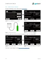
Figure 16. SW1 set to the ON position on Sensor Platform 2.
Figure 17. Relay 1 connection details.
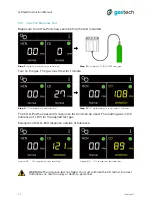
11.2 Sensor Platform Connections
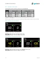
The HMI has 2 relay outputs to connect external equipment. The relays are activated
when the gas detected reaches the danger alarm level. See
.
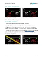
RS-485 is a balanced transmission standard. The end of the electrical transmission
line must have a termination resistor. Set the switch SW1 to the ON position to use the
built-in termination resistor for Sensor Platform 2.
Figure 18. Relay 2 connection details.
11.3 Sensor Platform Termination Resistor
11.4 Relay Connections
Содержание G-Shield Fire
Страница 1: ...INSTRUCTION MANUAL t 61 8 6108 0000 e info gastech com w gastech com t e w G SHIELD FIRE ...
Страница 36: ...G Shield Instruction Manual Version 1 36 15 6 HMI Dimensions Figure 45 HMI dimensions ...
Страница 37: ...G Shield Instruction Manual Version 1 37 15 7 HMI Enclosure Dimensions Figure 46 HMI enclosure dimensions ...


