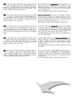
Abb. 1
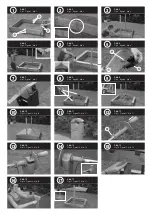
Zusammenstecken des Sandkastens.
Beginnen Sie mit 2 Stk. Seitenbretter (A).
Ausfräsungen nach oben! Weiter mit den
Seitenbrettern (B) und (C). Zum Schluss nochmals 2 Stk.
Seitenbretter (A). Achten Sie auf die Positionierung der Sei-
tenbretter (C) mit Loch!
Abb. 2
Stützbrettchen (D) an den Seitenwänden ohne Lochbohrung
mittig montieren. Verwenden Sie dazu Schraube (1).
Abb. 3
Montage der Dachsteher (E) mit Schrauben (5)(8)(9). Die
Dachsteher werden außenseitig montiert! Hinweis: Die Hut-
muttern sollen jeweils nach außen zeigen!
Abb. 4
Auflegen der Sitzbretter (F) und (G), ausrichten und mit
Schrauben (1) befestigen!
Abb. 5
Montage der farbigen Ecken (L) an allen vier Ecken mit
Schrauben (3).
Abb. 6
Einstecken des Sicherungsbolzen (N) in das Giebelbrett (H)
sowie Befestigen des Führungsschuh (O) mit Schrauben (4).
Achten Sie auf die vorgestanzten Lochpositionen!
Abb. 7
Einfädeln des Seils (10) in den Führungsschuh (O) lt. Abbil-
dung.
Einsetzen der vormontierten Giebelelemente (H) in die Dach-
steher (E) lt. Abbildung.
WICHTIG: Schneiden Sie aus dem Verpackungskarton vier
Kartonstreifen mit je ca. 10x5 cm aus und stecken Sie diese
zwischen Führungsschuh (O) und Dachsteher (E) als Ab-
standhalter für die weitere Montage der Firstlatten (J).
Abb. 8
Einsetzen der vormontierten Giebelelemente (H) in die Dach-
steher (E) lt. Abbildung.
WICHTIG: Schneiden Sie aus dem Verpackungskarton vier
Kartonstreifen mit je ca. 10x5 cm aus und stecken Sie diese
zwischen Führungsschuh (O) und Dachsteher (E) als Ab-
standhalter für die weitere Montage der Firstlatten (J).
Abb. 9
Montage der Firstlatten (J) mit Schrauben (2).
WICHTIG: Anschließend Kartonstreifen entfernen! Die Gie-
belelemente müssen sich in den Dach stehern (E) leicht be-
wegen können!
Abb. 10
Aufsetzen der Dachfolie mit Leisten (Q) und Befestigung mit
Schrauben (6)(8)(9).
Abb. 11
Montage der Kurbelhalterung (M) auf Dachsteher (E) mit
Schraube (3).
Abb. 12
Aufstecken der Kurbel (P) beidseitig auf die Alu miniumachse
(K) und Fixierung mit Splint (7).
TIPP: Die Splinte sind sorgfältig umzubiegen und ggf. mit
etwas Klebeband abzukleben!
Abb. 13
Einsetzen der vormontierten Kurbelachse in die Kurbelhalte-
rung (M) und Verschraubung mit Schraube (1).
HINWEIS: Die Leichtgängigkeit der Kurbel und die Brems-
funktion wird durch leichteres oder stärkeres Festziehen die-
ser Schrauben erreicht!
Abb. 14
Einfädeln des Seils (10) in die Kurbelachse lt. Abbildung!
ACHTUNG: Die Seile müssen beidseitig gleich stark ge-
spannt sein, um ein paralleles Hochfahren des Daches zu
garantieren!
Abb. 15
Einsetzen der Augenschutzplatte auf den Sicherungsbolzen (N).
Abb. 16
Zum Heben und Senken des Daches ist mit der zweiten
Hand am Dachsteher (E) entgegenzuhalten. Das verringert
die Hebelwirkung!
Abb. 17
Fertiger Aufbau! Der Sicherungsbolzen ist im geöffneten Zu-
stand
IMMER einzurasten.
HINWEIS: Der Sicherungsbolzen kann durch leichtes Anhe-
ben des Daches gelöst werden!
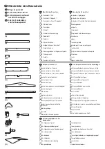
Stückliste Zubehör:
(1) 24 Stk. Spanplattenschrauben 40 mm
(2) 8 Stk. Spanplattenschrauben 50 mm
(3) 18 Stk. Spanplattenschrauben 20 mm
(4) 8 Stk. Rundkopfschrauben 20 mm
(5) 4 Stk. Schlossschrauben 55 mm
(6) 4 Stk. Schlossschrauben 60 mm
(7) 2 Stk. Splinte
(8) 8 Stk. Beilagscheiben klein
(9) 8 Stk. Hutmuttern
(10) 2 Stk. Seil, je ca. 117 cm
D
Fig. 1
Assemblage du bac à sable.
Commencez par 2 planches latérales (A).
Veillez à mettre les rainures vers le haut!
Continuez avec les planches latérales (B) et (C). Pour finir,
ajoutez encore 2 planches latérales (A). Veillez à bien positi-
onner les planches latérales (C) munies de trous!
Fig. 2
Montez les planchettes de renforcement au milieu des côtés
démunis de trous. Utilisez pour cela les vis (1).
Fig. 3
Montage des montants pour le toit (E) avec les vis (5)(8)(9).
Les montants doivent être fixés à l’extérieur! Veillez à ce que
les boulons à tête bombée soient dirigés vers l’extérieur!
Fig. 4
Poser les planches de siège (F) et (G), les positionner et les
fixer avec les vis (1).
Fig. 5
Assemblage des coins de couleur (L) aux quatre coins à
l’aide des vis (3).
Fig. 6
Introduire les boulons de sécurité (N) dans la planche de pi-
gnon (H) et fixer le galet de guidage (O) à l’aide des vis (4).
Veiller à la position des trous prépercés!
Fig. 7
Enfilez la corde (10) dans le galet de guidage (O) comme in-
diqué sur la photo.
IMPORTANT : coupez dans le carton d’emballage
4 languettes de carton d’environ 10x5 cm chacune et
placez-les entre le galet de guidage (O) et le montant pour le
toit (E) pour réserver un espace nécessaire à la poursuite du
montage des lattes faîtières (J).
Fig. 8
Placez les éléments de pignon (H) prémontés dans les mon-
tants du toit (E) comme indiqué sur la photo.
IMPORTANT : coupez dans le carton d’emballage
4 languettes de carton d’environ 10x5 cm chacune et
placez-les entre le galet de guidage (O) et le montant du toit
(E) pour réserver un espace nécessaire à la poursuite du
montage des lattes faîtières.
Fig. 9
Montage des lattes faîtières (J) au moyen de vis (2).
IMPORTANT : Enlever ensuite les languettes de carton! Les
éléments de pignon doivent pouvoir bouger légèrement
dans les montants (E)
F
Fig. 8
Put the preassembled gable elements (H) into the roof posts
(E) as illustrated above.
IMPORTANT: Cut four approx. 10x5 cm strips out of the
cardboard packaging and put them in between the guide
shoes (O) and the roof posts (E) as spacers for the top bars (J).
Fig. 9
Attach the top bars (J) using screws (2).
IMPORTANT: Remove the cardboard strips when you are
done! There must be enough space for the gable elements
to slide easily up and down the roof posts (E)!
Fig. 10
Put the tarpaulin and battens (Q) into place and use screws
(6)(8)(9) to attach.
Fig. 11
Mount the crank brackets (M) on the roof posts (E) using
screws (3).
Fig. 12
Put the cranks (P) on both ends of the aluminium spindle (K) and
fasten them with the cotter pins (7).
TIP: The cotter pins must be bent carefully and covered with
adhesive tape, if necessary!
Fig. 13
Put the preassembled crank axles into the crank
brackets (M) and fasten them with a screw (1).
NOTE: Smooth cranking and braking function are achieved
by tightening or loosening this screw!
Fig. 14
Thread the ropes (10) into the crank axles as illustrated
above!
ATTENTION: The ropes must be equally taut on both sides
to guarantee that the roof raises evenly!
Fig. 15
Put the eye protection plate on the safety lock bolt (N).
Fig. 16
When raising and lowering the roof, stabilize the roof post (E)
with your second hand to reduce the leverage!
Fig. 17
Construction finished! When the roof is raised, the safety
lock bolt must
ALWAYS be locked into place.
NOTE: Lift the roof a little to release the safety lock bolt!
Accessory parts list
(1) 24 particle board screws 40 mm
(2) 8 particle board screws 50 mm
(3) 18 particle board screws 20 mm
(4) 8 round-head screws 20 mm
(5) 4 coach bolts 55 mm
(6) 4 coach bolts 60 mm
(7) 2 cotter pins
(8) 8 small shims
(9) 8 cap nuts
(10) 2 ropes, approx. 117 cm each
Fig. 1
Putting together the sandbox.
Start with 2 sideboards (A). The notched edges must face
upwards! Add sideboards (B) and (C).
Finally, insert the other 2 sideboards (A). Make sure
that the sideboards (C) with a drilled hole are in correct
position!
Fig. 2
Screw the reinforcing boards (D) to the middle of the side
walls without a drilled hole, using screws (1).
Fig. 3
Mount the roof posts (E) using the screws (5)(8)(9). The
roof posts must be on the outside of the sandbox!
Note: The cap nuts must face outwards!
Fig. 4
Put the sitting boards (F) and (G) into place, adjust and
attach them with screws (1)!
Fig. 5
Attach one coloured corner unit (L) in each corner with
screws (3).
Fig. 6
Put the safety lock bolt (N) into the gable board (H) and
attach the guide shoe (O) with the screws (4). Use the
punched holes!
Fig. 7
Thread the rope (10) through the hole in the guide shoe (O)
as illustrated above.
GB


