112
Inspection and Maintenance
!
!
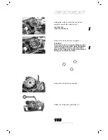
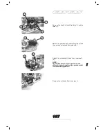
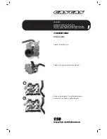
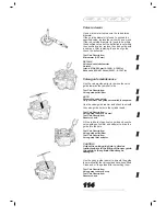
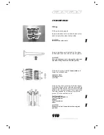
Remove the valves from the opposite side.
Use long-nosed pliers to remove the valve seals.
Detach the valve-spring washer.
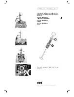
NOTE:
The valve detachment completes the standard
disassembly operation. If you had not detached
the valve guides for replacement after
inspecting their associated parts, follow the
instructions given in the valve-guide
maintenance section.
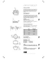
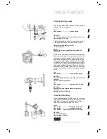
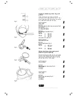
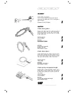
Cylinder-head deformation
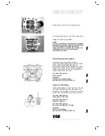
Decarbonize the combustión chamber.
Using a ruler and a feeler gauge, check the surface
of the cylinder-head gasket for signs of
deformation. Measure the clearance in several
places. If any of the clearance measurements is
found to exceed the service limit, replace the
cylinder head with a new one.
Tool Part Description:
Feeler gauge
DETAILS
Cylinder-head deformation
Service limit: 0.05 mm (0.002 in)
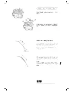
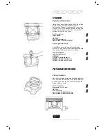
Valve-rod offsetting
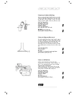
Using tapered blocks to hold the valve, measure
the valve-rod offsetting with a dial gauge, as
illustrated. If the offsetting is found to exceed the
service limit, replace the valve with a new one.
Tool Part Description:
Dial gauge (1/100 mm)
Tool Part Description:
Magnetic support
Tool Part Description:
Set of tapered blocks (100 mm)
DETAILS
Valve-rod offsetting
Service limit: 0.05 mm (0.002 in)
!
!
Содержание EC FSE 400 - SERVICE 2002 & 2003
Страница 1: ...SERVICE MANUAL MOTOR FSE400 450 2002 2003 SERVICE MANUAL MOTOR FSE400 450 2002 2003...
Страница 4: ...Engine Removal andInstallation 86 EngineRemovalandInstallation...
Страница 13: ...EngineDisassembly EngineDisassembly 96...
Страница 66: ...RegularMaintenance RegularMaintenance 154 Spark Plug 156 Engine Oil and Oil Filter 157 Engine oil pipework 159...
Страница 72: ...Notes Notas Notes 191...
Страница 73: ...Notas Notes 192...


