GARO Wallbox GLB Series Скачать руководство пользователя страница 38

EN

38

End User Instruction

A

B

C

E

D

A

B

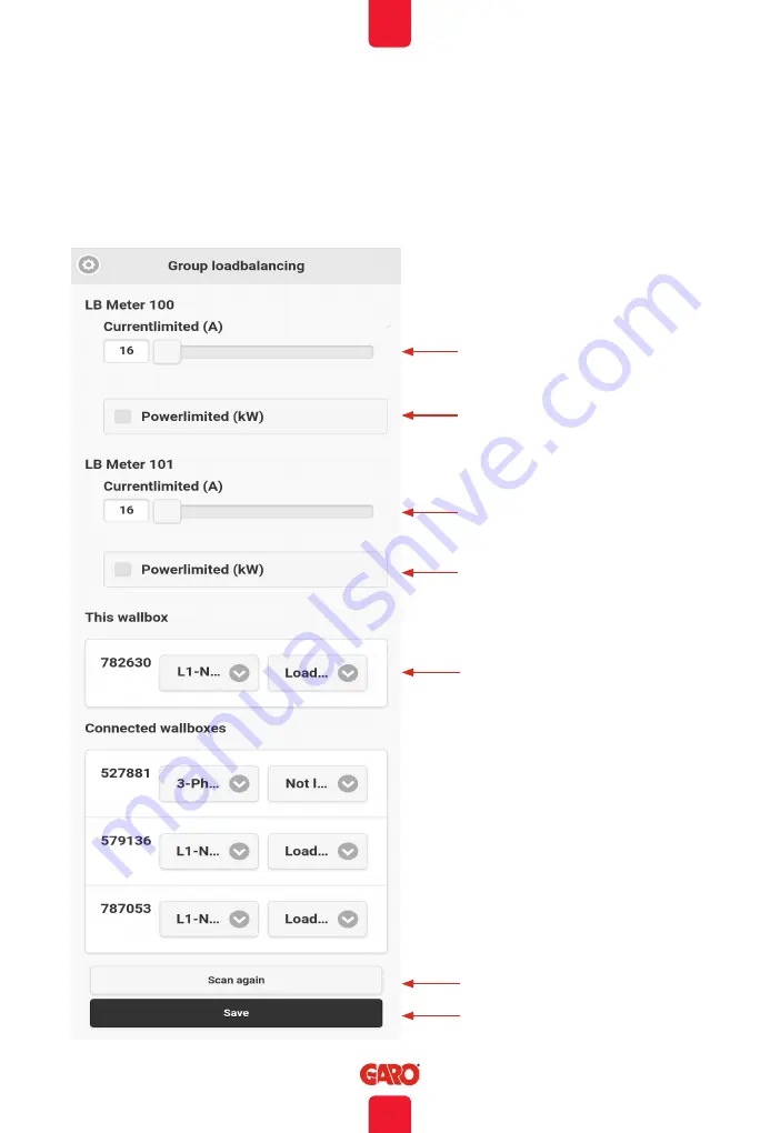
Dynamic Load Management (DLM) settings in the web interface (2pcs 
installed DLM energymeter)

(figure 38) 

A.  Select current or power 

limitation.

B.  Set maximum current (A) or 

power (kW).

C.  In the case of a single-phase 

charger, if the charger is to be 
controlled by load balancing, 
the phase assignation must be 
set. Three-phase chargers do 
not have phase assignation.

D.  Search for other connected 

GLB-Wallboxes. These are 
shown in the list through their 
respective serial numbers.

E.  Always save settings!

Содержание Wallbox GLB Series

Страница 1: ...EN GARO Wallbox GLB Assembly instructions End User Instruction EN manual 380185 4 0...

Страница 2: ...Charging electric vehicles 31 Resetting Conditioning of RCCB or RCBO 33 Connecting to the wallbox s Wi Fi access point AP 34 Web interface 35 Dynamic Load Management DLM settings in the web interface...

Страница 3: ...ly before trying to install operate or maintain the GLB Wallbox Indicates a potentially hazardous situation which could result in death or serious injury Indicates a potentially hazardous situation wh...

Страница 4: ...ging cable appears to be damaged Do not modify the equipment installation or any part of the product Do not touch the GLB Wallbox s terminals with fingers or any other objects Do not insert foreign ob...

Страница 5: ...ame supply Note that 1 phase charging is common in electric vehicles and L1 the GLB is used for this purpose Ventilation signal from EV is not supported Cord extension sets for charging cable is not a...

Страница 6: ...1 phase or 3 phase depending on GLB model Cable entrance from bottom side Custom only when extra functions in use Twisted pair cable for Modbus energy meter Twisted pair cable for Datalink communicat...

Страница 7: ...EN 7 Installation Instructions EN GARO Wallbox Assembly instructions User Instructions EN 380175 3 Box Contents Language labels GLB Wallbox Keys Drill template see the back of the box Manual...

Страница 8: ...Ferrules the diameter of the ferrule depends on the diameter of the power wiring and the construction Level Power drill Twisted pair cable Optional only when DLM is used Cable Suitable for Modbus com...

Страница 9: ...reaker with Overcurrent Protection RCBO can be connected in parallel This group of chargers must be protected by a backup fuse in the distribution box The backup fuse shall not exceed 125A Calculate t...

Страница 10: ...e appropriate earth fault equipment for the electrical installation NOTE Due to high currents for a long time in the cable there is a high risk of voltage drop if the cable is under dimensioned which...

Страница 11: ...EN 11 Installation Instructions Serial no SSID password Drill template see the back of the box figure 5 figure 6...

Страница 12: ...main fuse available range is 16A 63A SW1 is located at the center left hand side of the main board See photo 7 6 Set the dip switch SW2 according to your group fuse for the GLB Wallbox 6A 32A Dip swit...

Страница 13: ...t can be reduced using the switches on the mainboard refer to Mainboard simplified connection diagram figure 9 The power supply must be turned off before setting of the DIP switches figure 8 Dip Switc...

Страница 14: ...gulations Make sure that the cable is not electrified before start this step 8 Fill in the serial number of the main board in the Warranty form See QR code label at upper right corner of the main boar...

Страница 15: ...ation Instructions Language label is placed on the side 7 x T20 Label explaining charger status indication English information label MAX1 6Nm figure 12 figure 13 10 Turn on the electrical power to the...

Страница 16: ...etwork You find SSID and password on the rating label Type in 172 24 1 1 in your web browser and check that the GLB webinterface is visible This action confirms that the GLB Wallbox communication modu...

Страница 17: ...te Control function The wallbox is equipped with a potential free contact input where charging can be activated and deactivated The charger s remote control capability allows charging to be controlled...

Страница 18: ...d current transformer Note the energy meter s Modbus address must be set to 2 100 or 101 Adress 2 Recommended for a stand alone GLB Wallbox Setting for SW1 CC2 is valid and charging process are paused...

Страница 19: ...ection diagram Note Modbus connection between energy meter and GLB must be connected as following A energy meter to A GLB E meter terminal and B energy meter to B GLB E meter terminal Config energy me...

Страница 20: ...ternal energy meter installed the Modbus connection of the external meter is to be connected in parallel with the internal energy meter terminals E meter on the main board SW1 Dip 1 3 Main fuse A in e...

Страница 21: ...lar wind etc GNM3D LP RS485 GNM3T LP RS485N current transformer 3 phase Max current is based installed current transformer Note the energy meter s Modbus address must be set to 100 and 101 for the 2nd...

Страница 22: ...etween wallboxes Example of installation Data Link permitted connection via external junction boxes figure 20 0000 0 GLB Wi Fi GLB Standard GLB Standard GLB Standard GLB Standard Data Link Data Link D...

Страница 23: ...ent DLM setting inthe web interface It should be noted that SW1 DIP 1 3 does not have a function for group load balancing Instead group balancing is performed in the GLB Master s web interface see sec...

Страница 24: ...lling the RFID reader figure 22 Turn off the power to the GLB Wallbox Install the RFID reader as shown in the image above DIP switches on the RFID card should be set to ON mode FUSE 2AT SW2 SW1 SW3 fi...

Страница 25: ...the master wallbox is defined as master ensure the switch SW1 DIP 5 is set to ON Note It is only possible to have one Master GLB in a system when connecting GLB Wallboxes with the datalink bus If sev...

Страница 26: ...k cable must be electrically terminated in the first and last wallboxes via switch SW1 DIP 6 on the main board In the below example the switch SW1 DIP 6 is to be set to ON in wallboxes no 1 and 5 and...

Страница 27: ...00 Twisted pair Cable Suitable for modbus communication Wallbox 1 Wallbox 2 Wallbox 3 Wallbox 4 Wallbox 5 Twisted pair Junctionbox Junctionbox Junctionbox Junctionbox GLB Wi Fi GLB Standard Data Link...

Страница 28: ...d B to B see figure 27 figure 28 Config SW1 DIP 5 6 see figure 27 figure 28 If you want to use LAN cable to access the GLB Wallbox web interface you can install a LAN cable to the RJ45 port on the com...

Страница 29: ...rent A 16A Factory default SW3 figure 30 Mainboard simplified connection diagram Ext charge control open on close off Remote control signal can be set in inverse function SW3 Reset button Press down 3...

Страница 30: ...EN 30 Installation Instructions 205 124 422 Dimensional drawing figure 31...

Страница 31: ...y indicates charging in progress 3 Stop charging As a rule the GLB Wallbox socket and vehicle inlet locks the cable As a result charging must be stopped from the vehicle before the cable is removed Te...

Страница 32: ...le eg status Rapid flashing green device waiting for authorization eg RFID tag Shifting blue light intensity device connected to vehicle charging in progress Solid blue light RFID accepted waiting to...

Страница 33: ...1 Disconnect the car 2 Unlock the front cover with the key provided 3 Open the front cover A figure 31 by sliding it downwards 4 Reset the circuit breaker When conditioning press the test button then...

Страница 34: ...n the box below for future reference 3 Identify the wallbox s SSID name in the wireless network display on your phone tablet or computer Connect to the wallbox s wireless network and enter the passwor...

Страница 35: ...ould use the address chargebox garo se in the web browser Your mobile tablet PC must be connected to same network as your GLB Wallbox DLM settings Dynamic Load Management and require external energy m...

Страница 36: ...EN 36 End User Instruction Main menu Doubleclick on the GARO symbol and extended information shows...

Страница 37: ...act kW where relevant A Select current or power limitation B Set maximum current A or power kW C In the case of a single phase charger if the charger is to be controlled by load balancing the phase as...

Страница 38: ...wer limitation B Set maximum current A or power kW C In the case of a single phase charger if the charger is to be controlled by load balancing the phase assignation must be set Three phase chargers d...

Страница 39: ...ld to be used for entering the name of the person using the tag for example When RFID is activated a registered RFID tag must be held out in order to activate the GLB Wallbox after the vehicle has bee...

Страница 40: ...i A B C D figure 41 figure 42 A Choose to connect via router B Enter your network name SSID C Enter your network password D Press save NOTE When the GLB Wallbox is connected to a local network use the...

Страница 41: ...ll status Accesspunkt efter 10 minuter Connect GLB Wallbox to a local network via ethernet using DHCP server figure 43 figure 44 A B C A Choose to obtain IP address automatically in the Ethernet setti...

Страница 42: ...ing a static IP address If the data entered is incorrect or the connection is unsuccessful for any other reason the device will return to access point mode after around 10 minutes A Choose Static IP B...

Страница 43: ...the web interface Firmware update process for GLB Wallbox connected to internet via Wifi or LAN By Computer Android mobile or tablet 1 Open https www webel online se wifi and download the file device...

Страница 44: ...or moisture Do not use cleaning solvents to clean any of the GLB Wallbox s components The outside of the GLB Wallbox the charging cable and the end of the charging cable should be periodically wiped...

Страница 45: ...aker Solid red light for 3 sec RFID tag not accepted Red fast flash DC current 6mA charging has stopped Constant yellow light Broken cable Check cable Flashing yellow light Motor lock socket not in la...

Страница 46: ...sity EV charging in progress Shifting red blue Software upgrade in progress Shifting blue black Chargesession not enabled due to scheduled mood Solid green Charger in idle waiting for EV to connect Gr...

Страница 47: ...ion method TT TN and IT system Charging type Mode 3 Protection class IP44 Mechanical impact resistance IK08 Temperature range 250 C 450 C without direct sunlight Storage temperature 350 C 550 C Instal...

Страница 48: ...48 EN GARO AB Box 203 SE 335 25 Gnosj Phone 46 0 370 33 28 00 info garo se garo se...

Отзывы: