


6
The Categories of the web interface
The web interface is divided in five different categories. These has different levels of
accessibility:
• State (read only)
–
The startup page of the web interface gives an overview of the charger
status for charging sessions, meter values, connectivity, firmware and alarms. The state view
can only be used for reading values and parameters. Nothing can be changed from here,
”State” is accessible for everyone with access to the web interface address (192.168.123.123)
• Settings
–
Here you can access the most fundamental settings for operating and backend
connection of the charger. From here you can configure type of connection, OCPP protocol
and backend address. You can also activate or de‐activate the chargers. RFID‐readers and
turn down the current limit of the outlets.
”Settings” demands ”operator” or ”manufacturer” permission.
• Operator
–
Here you’ll find all the parameters from the “Settings” view and also more
advanced settings when it comes to connectivity, communication, monitoring, authentication
and behavior during operation.
”Operator” demands “operator” or “manufacturer” permission. (operator / yellow_zone )
version 4.2) (operator / cherry_zone )version 4.3)
• Manufacturer
–
Here you have access to all hardware settings of the charger, such as
charging equipment, max hardware current limit, model, vendor, serial number and the mas-
ter/slave setup.
These settings should not be changed after the charger has left the factory unless the charger is
rebuilt or modified.
”Manufacturer” demands “manufacturer” permission. Be aware that wrongly made changes of
these parameters could result in serious consequenses of the chargers operating behavior.
• Documentation
– Is divided into two subcategories;
• Error Documentation
,
where error codes are listed together with possible cause and solu-
tion and
OCPP Keys Documentation,
which lists OCPP‐commands/keys for the currently
running FW version.
”Documentation” is accessible for everyone with access to the web interface address
(192.168.123.123).
Содержание LS4 Wallmounted
Страница 1: ...LS4 GLB Operational Instructions...
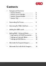
Страница 3: ...Interior Bottom Interior Lower Middle 2...
Страница 4: ...3 Interior Upper Middle Interior Top...
Страница 5: ...4 Connecting the Laptop computer...
Страница 9: ...8 Setup of DLM with external Secondary Meter...
Страница 14: ...13...
Страница 15: ...14...


