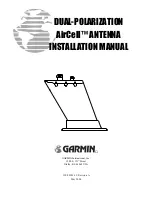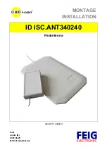
DUAL-POLARIZATION AirCell™ ANTENNA INSTALLATION MANUAL
Page 4
P/N 190-00189-12
Rev. A
3. INSTALLATION
PROCEDURE
3.1. UNIT AND ACCESSORIES
The Dual-polarization AirCell Antenna is available under the following part number:
ITEM
GARMIN P/N
AirCell Antenna, Dual Polarization,
includes:
Cellular Antenna, Dual Polarization
(700-00013-00)
AirCell Antenna Installation Kit
(013-00059-00)
010-10278-00
3.2. MISCELLANEOUS OPTIONS
None.
3.3. INSTALLATION ACCESSORIES REQUIRED BUT NOT PROVIDED
None.
3.4. ANTENNA INSTALLATION
Proper design for the installation of the antenna is critical for the system performance and meeting FAA
regulations, especially on pressurized aircraft. Antenna installation requires proper FAA approval and must
meet the requirements of FAA FAR 23.571 or FAR 25.571.
NOTE
Rule changes over recent years require that penetration in pressurized aircraft be analyzed. FAA AC
43.13-1B does not properly address the new rules for the installation of antennas in pressurized aircraft. An
analysis is required to determine that the installation will not cause cracks and structural damage due to
loads placed on antennas. This analysis is usually performed by a DER and documented on FAA Form
8110-3 and included as approved data on FAA Form 337.
NOTE
It is desirable to have at least 18” and preferably 36” of separation from other antennas. Please call AirCell
Customer Service/Technical Support to discuss installs with less separation.
When using the Low Profile Antenna (CI 5000-1), the antenna must be mounted on the bottom of the
aircraft on the lowest possible portion of the airframe in level flight. Best performance will result if the
antenna is located forward or aft of the wing area. If possible, do not position the antenna under the wing
and NEVER on the tail upsweep (see Figure 1 for more complete information on antenna placement).
NOTE
All antenna installations must comply with the applicable FARs.
IMPORTANT
The base of antennas must be metal to metal bonded with the aircraft skin. For the CI 5000-1 Antenna, no
ground is provided via the mounting screws as the base plate screw holes do not have metal sleeves. Be
sure to remove paint on aircraft skin, pre-treat, and treat with Alodine or equivalent conductive corrosion
inhibiting treatment.
CAUTION
Do not use construction grade RTV sealant or sealants containing acetic acid. These sealants may damage
the electrical connections to the antenna. Use of these type sealants may void the antenna warranty.

