


GTN 725/750 TSO Installation Manual
Page 2-1
190-01007-02
Rev. A
2. INSTALLATION OVERVIEW
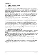
2.1 Introduction
Always follow acceptable avionics installation practices per AC 43.13-1B, AC 43.13-2B, or later FAA
approved revisions of these documents. The GPS/WAAS installation instructions have been prepared to
meet the guidance material contained in AC 20-138A “Airworthiness Approval of Global Navigation
Satellite System (GNSS) Equipment”. The communications installation instructions have been prepared
to meet the guidance material defined by AC 20-67B, “Airborne VHF Communications Equipment
Installations”.
2.2 Minimum
System
Configuration
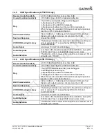
2.2.1 VFR
Installation
The minimum GTN installation requires the following items for a VFR Installation:
•
GTN (installed in the aircraft manufacturer approved location for 6.25” wide avionics equipment)
•
GPS antenna is required for GPS navigation functions.
•
An external CDI is required for installations using the VOR navigation and glideslope
information.
•
A NAV antenna is required for VHF NAV functions.
•
A COM antenna is required for COM functions.
VFR installations must be placarded “GPS LIMITED TO VFR USE ONLY” in clear view of the pilot.
2.2.2
IFR GPS Installation
In order for the GTN to be utilized for IFR GPS Navigation, the criteria in Section 2.2.1 must be met in
addition to the following:
•
An External CDI/HSI indicator must be installed in the pilot’s primary field-of-view (or in the
aircraft manufacturer approved mounting location). The indicator must have a vertical deviation
indicator (glideslope) in order to perform VNAV operations/approaches.
•
Any annunciation required for Source Selection or IFR GPS Navigation must meet the acceptable
field-of-view requirements.
NOTE
To take full advantage of the GTN capabilities, an optional barometric altitude source is
recommended for automatic sequencing of fix-to-altitude (FA) and hold-to-altitude (HA)
leg types. If no barometric altitude data is provided to the GTN, FA and HA legs must be
manually sequenced.
Содержание GTN 725
Страница 1: ...190 01007 02 TBD 2010 Rev A GTN 725 750 TSO Installation Manual GTN 725 and GTN 750...
Страница 2: ......
Страница 26: ...Page 1 14 GTN 725 750 TSO Installation Manual Rev A 190 01007 02 This page intentionally left blank...
Страница 38: ...Page 2 12 GTN 725 750 TSO Installation Manual Rev A 190 01007 02 This page intentionally left blank...
Страница 48: ...Page 3 10 GTN 725 750 TSO Installation Manual Rev A 190 01007 02 This page intentionally left blank...
Страница 114: ...Page 5 38 GTN 725 750 TSO Installation Manual Rev A 190 01007 02 This page intentionally left blank...
Страница 116: ...Page 6 2 GTN 725 750 TSO Installation Manual Rev A 190 01007 02 This page intentionally left blank...
Страница 118: ...Page 7 2 GTN 725 750 TSO Installation Manual Rev A 190 01007 02 This page intentionally left blank...
Страница 120: ...Page A 2 GTN 725 750 TSO Installation Manual Rev A 190 01007 02 This page intentionally left blank...
Страница 130: ...Page B 10 GTN 725 750 TSO Installation Manual Rev A 190 01007 02 This page intentionally left blank...
Страница 132: ...Page C 2 GTN 725 750 TSO Installation Manual Rev A 190 01007 02 This page intentionally left blank...
Страница 133: ...GTN 725 750 TSO Installation Manual Page C 3 190 01007 02 Rev A Figure C 1 GTN Mounting Rack Dimensions...
Страница 134: ...Page C 4 GTN 725 750 TSO Installation Manual Rev A 190 01007 02 Figure C 2 GTN Mounting Rack Installation...
Страница 135: ...GTN 725 750 TSO Installation Manual Page C 5 190 01007 02 Rev A Figure C 3 GTN Mounting Rack Assembly...
Страница 136: ...Page C 6 GTN 725 750 TSO Installation Manual Rev A 190 01007 02 Figure C 4 GTN Recommended Panel Cutout Dimensions...
Страница 138: ...Page D 2 GTN 725 750 TSO Installation Manual Rev A 190 01007 02 This page intentionally left blank...
Страница 139: ...GTN 725 750 TSO Installation Manual Page D 3 190 01007 02 Rev A Figure D 1 GTN System Interface Diagram...
Страница 141: ...GTN 725 750 TSO Installation Manual Page D 5 190 01007 02 Rev A Figure D 2 GTN 750 Typical Installation Sheet 2 of 2...
Страница 142: ...Page D 6 GTN 725 750 TSO Installation Manual Rev A 190 01007 02 Figure D 3 GTN 725 Typical Installation Sheet 1 of 2...
Страница 143: ...GTN 725 750 TSO Installation Manual Page D 7 190 01007 02 Rev A Figure D 3 GTN 725 Typical Installation Sheet 2 of 2...
Страница 146: ...Page D 10 GTN 725 750 TSO Installation Manual Rev A 190 01007 02 Figure D 5 GTN Antenna Interconnect Sheet 1 of 3...
Страница 147: ...GTN 725 750 TSO Installation Manual Page D 11 190 01007 02 Rev A Figure D 5 GTN Antenna Interconnect Sheet 2 of 3...
Страница 148: ...Page D 12 GTN 725 750 TSO Installation Manual Rev A 190 01007 02 Figure D 5 GTN Antenna Interconnect Sheet 3 of 3...
Страница 149: ...GTN 725 750 TSO Installation Manual Page D 13 190 01007 02 Rev A Figure D 6 GTN Main Indicator Interconnect...
Страница 150: ...Page D 14 GTN 725 750 TSO Installation Manual Rev A 190 01007 02 Figure D 7 GTN Autopilot Interconnect...
Страница 151: ...GTN 725 750 TSO Installation Manual Page D 15 190 01007 02 Rev A Figure D 8 GTN Traffic Interconnect...
Страница 152: ...Page D 16 GTN 725 750 TSO Installation Manual Rev A 190 01007 02 Figure D 9 GTN Transponder Interconnect...
Страница 153: ...GTN 725 750 TSO Installation Manual Page D 17 190 01007 02 Rev A Figure D 10 Dual GTN to Single GDU Interconnect...
Страница 157: ...GTN 725 750 TSO Installation Manual Page D 21 190 01007 02 Rev A Figure D 13 GTN GDL 69 69A Interconnect...
Страница 159: ...GTN 725 750 TSO Installation Manual Page D 23 190 01007 02 Rev A Figure D 14 Audio Panel Interconnect Sheet 2 of 2...
Страница 162: ...Page D 26 GTN 725 750 TSO Installation Manual Rev A 190 01007 02 Figure D 16 Air Data IRU AHRS ARINC 429 Interconnect...
Страница 163: ...GTN 725 750 TSO Installation Manual Page D 27 190 01007 02 Rev A Figure D 17 GAD 42 Interconnect...
Страница 164: ...Page D 28 GTN 725 750 TSO Installation Manual Rev A 190 01007 02 Figure D 18 VOR ILS Indicator Interconnect...
Страница 170: ...Page D 34 GTN 725 750 TSO Installation Manual Rev A 190 01007 02 Figure D 24 Parallel Slip Code DME Tuning Interconnect...
Страница 171: ...GTN 725 750 TSO Installation Manual Page D 35 190 01007 02 Rev A Figure D 25 Heading Synchro Interconnect...
Страница 172: ...Page D 36 GTN 725 750 TSO Installation Manual Rev A 190 01007 02 Figure D 26 GPS Annunciator Interconnect...
Страница 173: ...GTN 725 750 TSO Installation Manual Page D 37 190 01007 02 Rev A Figure D 27 NAV Source Select Annunciator Interconnect...
Страница 175: ...GTN 725 750 TSO Installation Manual Page D 39 190 01007 02 Rev A Figure D 29 Switches Interconnect...
Страница 176: ...Page D 40 GTN 725 750 TSO Installation Manual Rev A 190 01007 02 This page intentionally left blank...
Страница 177: ......
Страница 178: ......


