


GTN 725/750 TSO Installation Manual
Page 5-25
190-01007-02
Rev. A
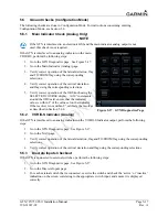
5.6.7
Altitude Encoder or Air Data Computer Check
The GTN can receive altitude data from an external source. This check verifies that the GTN is receiving
data from these sources. Ensure that the GTN is powered on and in normal mode. If the following steps
do not perform correctly, check the electrical connections and configuration setup.
1.
Go to the map page from the home page in normal mode.
2.
Touch the Menu button.
3.
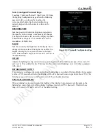
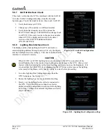
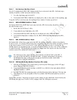
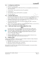
Under ‘Map Data Fields’ touch the Change Data Fields button. See Figure 5-22.
4.
Touch one of the four data fields and configure it to display PRESS ALT—Pressure Altitude.
5.
If there are multiple altitude sources providing data to the GTN, remove power from all but one
source.
6.
Verify that PRESS—ALT is being displayed and agrees with the active altitude source.
NOTE
After applying power to an altitude source it may take several minutes to warm up.
During the warm-up period the altitude display on the GTN will be dashed out.
7.
If there are multiple altitude sources, remove power from the currently active source and apply
power to another source that has not been checked.
8.
Repeat steps 5-7 until all available sources have been checked.
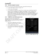
5.6.8 AHRS/IRU
Interface
Check
The GTN can receive heading data from an external source. This check verifies that the GTN is receiving
data from these units. Ensure the GTN is turned on and in normal mode. If the following steps do not
perform correctly, check the electrical connections and configuration setup.
1.
Go to the map page from the home page in normal
mode.
2.
Touch the Menu button.
3.
Under ‘Map Data Fields’ touch the Change Data
Fields button. See Figure 5-22.
4.
Touch one of the four data fields and configure it
to display BRG — Bearing to Current Waypoint.
NOTE
If a Sandel EHSI or an ARINC 429 EFIS is also
installed, ensure that it is turned off so that it does
not supply heading to the GTN. Verify that the
HDG field displays valid heading data.
5.
Remove power from the heading source and
verify that the heading in the BRG field is dashed
out.
Figure 5-22. Map Menu Page
Содержание GTN 725
Страница 1: ...190 01007 02 TBD 2010 Rev A GTN 725 750 TSO Installation Manual GTN 725 and GTN 750...
Страница 2: ......
Страница 26: ...Page 1 14 GTN 725 750 TSO Installation Manual Rev A 190 01007 02 This page intentionally left blank...
Страница 38: ...Page 2 12 GTN 725 750 TSO Installation Manual Rev A 190 01007 02 This page intentionally left blank...
Страница 48: ...Page 3 10 GTN 725 750 TSO Installation Manual Rev A 190 01007 02 This page intentionally left blank...
Страница 114: ...Page 5 38 GTN 725 750 TSO Installation Manual Rev A 190 01007 02 This page intentionally left blank...
Страница 116: ...Page 6 2 GTN 725 750 TSO Installation Manual Rev A 190 01007 02 This page intentionally left blank...
Страница 118: ...Page 7 2 GTN 725 750 TSO Installation Manual Rev A 190 01007 02 This page intentionally left blank...
Страница 120: ...Page A 2 GTN 725 750 TSO Installation Manual Rev A 190 01007 02 This page intentionally left blank...
Страница 130: ...Page B 10 GTN 725 750 TSO Installation Manual Rev A 190 01007 02 This page intentionally left blank...
Страница 132: ...Page C 2 GTN 725 750 TSO Installation Manual Rev A 190 01007 02 This page intentionally left blank...
Страница 133: ...GTN 725 750 TSO Installation Manual Page C 3 190 01007 02 Rev A Figure C 1 GTN Mounting Rack Dimensions...
Страница 134: ...Page C 4 GTN 725 750 TSO Installation Manual Rev A 190 01007 02 Figure C 2 GTN Mounting Rack Installation...
Страница 135: ...GTN 725 750 TSO Installation Manual Page C 5 190 01007 02 Rev A Figure C 3 GTN Mounting Rack Assembly...
Страница 136: ...Page C 6 GTN 725 750 TSO Installation Manual Rev A 190 01007 02 Figure C 4 GTN Recommended Panel Cutout Dimensions...
Страница 138: ...Page D 2 GTN 725 750 TSO Installation Manual Rev A 190 01007 02 This page intentionally left blank...
Страница 139: ...GTN 725 750 TSO Installation Manual Page D 3 190 01007 02 Rev A Figure D 1 GTN System Interface Diagram...
Страница 141: ...GTN 725 750 TSO Installation Manual Page D 5 190 01007 02 Rev A Figure D 2 GTN 750 Typical Installation Sheet 2 of 2...
Страница 142: ...Page D 6 GTN 725 750 TSO Installation Manual Rev A 190 01007 02 Figure D 3 GTN 725 Typical Installation Sheet 1 of 2...
Страница 143: ...GTN 725 750 TSO Installation Manual Page D 7 190 01007 02 Rev A Figure D 3 GTN 725 Typical Installation Sheet 2 of 2...
Страница 146: ...Page D 10 GTN 725 750 TSO Installation Manual Rev A 190 01007 02 Figure D 5 GTN Antenna Interconnect Sheet 1 of 3...
Страница 147: ...GTN 725 750 TSO Installation Manual Page D 11 190 01007 02 Rev A Figure D 5 GTN Antenna Interconnect Sheet 2 of 3...
Страница 148: ...Page D 12 GTN 725 750 TSO Installation Manual Rev A 190 01007 02 Figure D 5 GTN Antenna Interconnect Sheet 3 of 3...
Страница 149: ...GTN 725 750 TSO Installation Manual Page D 13 190 01007 02 Rev A Figure D 6 GTN Main Indicator Interconnect...
Страница 150: ...Page D 14 GTN 725 750 TSO Installation Manual Rev A 190 01007 02 Figure D 7 GTN Autopilot Interconnect...
Страница 151: ...GTN 725 750 TSO Installation Manual Page D 15 190 01007 02 Rev A Figure D 8 GTN Traffic Interconnect...
Страница 152: ...Page D 16 GTN 725 750 TSO Installation Manual Rev A 190 01007 02 Figure D 9 GTN Transponder Interconnect...
Страница 153: ...GTN 725 750 TSO Installation Manual Page D 17 190 01007 02 Rev A Figure D 10 Dual GTN to Single GDU Interconnect...
Страница 157: ...GTN 725 750 TSO Installation Manual Page D 21 190 01007 02 Rev A Figure D 13 GTN GDL 69 69A Interconnect...
Страница 159: ...GTN 725 750 TSO Installation Manual Page D 23 190 01007 02 Rev A Figure D 14 Audio Panel Interconnect Sheet 2 of 2...
Страница 162: ...Page D 26 GTN 725 750 TSO Installation Manual Rev A 190 01007 02 Figure D 16 Air Data IRU AHRS ARINC 429 Interconnect...
Страница 163: ...GTN 725 750 TSO Installation Manual Page D 27 190 01007 02 Rev A Figure D 17 GAD 42 Interconnect...
Страница 164: ...Page D 28 GTN 725 750 TSO Installation Manual Rev A 190 01007 02 Figure D 18 VOR ILS Indicator Interconnect...
Страница 170: ...Page D 34 GTN 725 750 TSO Installation Manual Rev A 190 01007 02 Figure D 24 Parallel Slip Code DME Tuning Interconnect...
Страница 171: ...GTN 725 750 TSO Installation Manual Page D 35 190 01007 02 Rev A Figure D 25 Heading Synchro Interconnect...
Страница 172: ...Page D 36 GTN 725 750 TSO Installation Manual Rev A 190 01007 02 Figure D 26 GPS Annunciator Interconnect...
Страница 173: ...GTN 725 750 TSO Installation Manual Page D 37 190 01007 02 Rev A Figure D 27 NAV Source Select Annunciator Interconnect...
Страница 175: ...GTN 725 750 TSO Installation Manual Page D 39 190 01007 02 Rev A Figure D 29 Switches Interconnect...
Страница 176: ...Page D 40 GTN 725 750 TSO Installation Manual Rev A 190 01007 02 This page intentionally left blank...
Страница 177: ......
Страница 178: ......


