


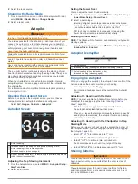


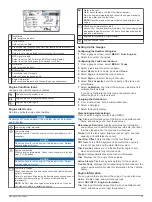


MARPA Targeting Symbols
Acquiring a target. Concentric, dashed green rings radiate from
the target while the radar is locking onto it.
Target has been acquired. A solid green ring indicates the
location of a target that the radar has locked onto. A dashed
green line attached to the circle indicates the projected course
over ground or the GPS heading of the target.
Dangerous target is in range. A red ring flashes from the target
while an alarm sounds and a message banner appears. After
the alarm has been acknowledged, a solid red dot with a dashed
red line attached to it indicates the location and the projected
course over ground or the GPS heading of the target. If the safe-
zone collision alarm has been set to Off, the target flashes, but
the audible alarm does not sound and the alarm banner does
not appear.
Target has been lost. A solid green ring with an X through it
indicates that the radar could not lock onto the target.
Closest point of approach and time to closest point of approach
to a dangerous target.
Assigning a MARPA Tag to an Object
Before you can use MARPA, you must have a heading sensor
connected and an active GPS signal. The heading sensor must
provide the NMEA 2000 parameter group number (PGN)
127250 or the NMEA 0183 HDM or HDG output sentence.
1
From a radar screen, select an object or location.
2
Select
Acquire Tgt.
>
MARPA Target
.
Removing a MARPA Tag from a Targeted Object
1
From the Radar screen, select a MARPA target.
2
Select
MARPA Target
>
Remove
.
Viewing Information about a MARPA-tagged Object
You can view the range, bearing, speed, and other information
about a MARPA-tagged object.
1
From a radar screen, select a targeted object.
2
Select
MARPA Target
.
Viewing a List of AIS and MARPA Threats
From any Radar screen or the Radar overlay, you can view and
customize the appearance of a list of AIS and MARPA threats.
1
From a Radar screen, select
MENU
>
Layers
>
Other
Vessels
>
List
>
Show
.
2
Select the type of threats to include in the list.
Showing AIS Vessels on the Radar Screen
AIS requires the use of an external AIS device and active
transponder signals from other vessels.
You can configure how other vessels appear on the Radar
screen. If any setting (except the AIS display range) is
configured for one radar mode, the setting is applied to every
other radar mode. The details and projected heading settings
configured for one radar mode are applied to every other radar
mode and to the Radar overlay.
1
From a Radar screen or the Radar overlay, select
MENU
>
Other Vessels
>
AIS
.
2
Select an option:
• To indicate the distance from your location within which
AIS vessels appear, select
Display Range
, and select a
distance.
• To show details about AIS-activated vessels, select
Details
>
Show
.
• To set the projected heading time for AIS-activated
vessels, select
Proj. Heading
, and enter the time.
• To show the tracks of AIS vessels, select
Trails
, and
select the length of the track that appears.
VRM and EBL
The variable range marker (VRM) and the electronic bearing line
(EBL) measure the distance and bearing from your boat to a
target object. On the Radar screen, the VRM appears as a circle
that is centered on the present location of your boat, and the
EBL appears as a line that begins at the present location of your
boat and intersects the VRM. The point of intersection is the
target of the VRM and the EBL.
Showing and Adjusting the VRM and the EBL
You can adjust the diameter of the VRM and the angle of the
EBL, which moves the intersection point of the VRM and the
EBL. The VRM and the EBL configured for one mode are
applied to all other radar modes.
1
From a radar screen, select
MENU
>
Radar Options
>
VRM/
EBL
.
2
To adjust the VRM/EBL, select the arrows on the
VRM/EBL
button.
3
Select a new location for the intersection point of the VRM
and the EBL
4
Select
Done
Measuring the Range and Bearing to a Target Object
Before you can adjust the VRM and the EBL, you must show
them on the Radar screen (
Showing and Adjusting the VRM and
1
From a Radar screen, select the target location.
2
Select
Measure
.
The range and the bearing to the target location appear in the
upper-left corner of the screen.
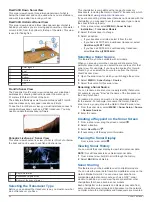
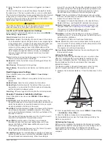
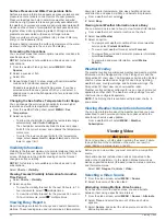
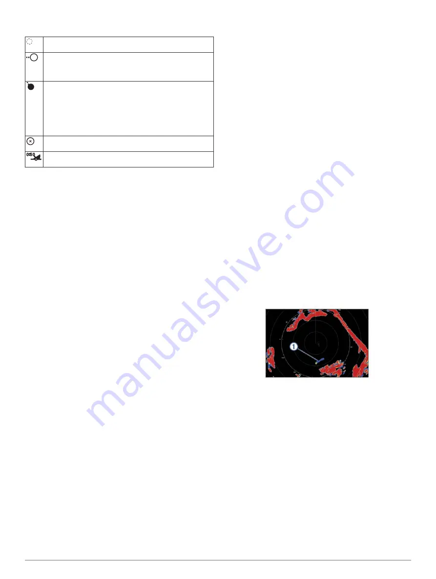
Echo Trails
The echo trails feature enables you to track the movement of
vessels on the radar display. As a vessel moves, you can see a
faint trail
À
of the vessel's wake. You can change the length of
time the trail is displayed.
NOTE:
Depending upon the radar in use, the settings configured
for use in one radar mode may or may not be applied to other
radar modes or to the radar overlay.
NOTE:
This feature is not available on xHD open array or
HD/HD+ radome models.
Turning on Echo Trails
From a radar screen, select
MENU
>
Radar Options
>
Echo
Trails
>
Display
.
Adjusting the Length of the Echo Trails
1
From a radar screen or the radar overlay, select
MENU
>
Radar Options
>
Echo Trails
>
Time
.
2
Select the length of the trail.
Clearing the Echo Trails
You can remove the echo trails from the radar screen to reduce
the clutter on the screen.
From a radar screen, select
MENU
>
Radar Options
>
Echo
Trails
>
Clear Trails
.
32
Radar
Содержание GPSMAP 1000 Series
Страница 1: ...GPSMAP 1000 1200SERIES Owner sManual...
Страница 8: ......
Страница 70: ...support garmin com June 2018 190 02145 00_0D...


