background image

GPS 155XL/GNC 300XL Installation Manual

P/N 190-00067-22  Rev E   Page 3-3

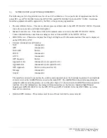
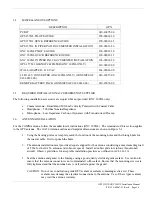
3.4

MISCELLANEOUS OPTIONS

DESCRIPTION

GPN

PC KIT

010-10075-00

GPS 155XL PILOT’S GUIDE190-00067-20

GPS 155XL QUICK REFERENCE GUIDE

190-00067-21

GPS 155XL IN PIPER PA32 DOCUMENTED INSTALLATION

190-00067-26

GNC 300XL PILOT’S GUIDE190-00067-30

GNC 300XL QUICK REFERENCE GUIDE

190-00067-31

GNC 300XL IN PIPER PA32 DOCUMENTED INSTALLATION

190-00067-36

GPS 1.57542 GHz NOTCH FILTER (GNC 300XL ONLY)

330-00067-00

WALL ADAPTER - 110 VAC

362-00014-00

28 TO 14V CONVERTER (GNC 300XL ONLY) (CONSISTS OF
011-00181-00)

010-10057-00

REMOTE BATTERY PACK (CONSISTS OF 011-00182-00)

010-10074-00

3.5

REQUIRED INSTALLATION ACCESSORIES NOT SUPPLIED

The following installation accessories are required but not provided (GNC 300XL only).


Comm Antenna—Broad Band 50 Ohm Vertically Polarized with Coaxial Cable


Headphones—500 Ohm Nominal Impedance


Microphone—Low Impedance Carbon or Dynamic with Transistorized Preamp

3.6

ANTENNA INSTALLATION

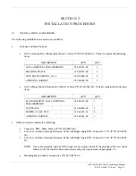
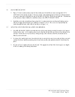
For the COMM antenna, follow the manufacturer's instructions (GNC 300XL).  The remainder of this section applies
to the GPS antenna.  The GA 56 Antenna outline and footprint dimensions are shown in Figure 5-1.

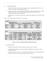
1. Using the backing plate as a template, mark the location of the mounting holes and the through hole for

the coaxial cable.  Drill or punch the holes.

2. The antenna installation must provide adequate support for the antenna considering a maximum drag load

of 5 lbs. for the GA 56 antennas (at subsonic speed).  Install a doubler plate to reinforce thin skinned
aircraft.  Observe guidelines for acceptable installation practices as outlined in AC 43.13-2A.

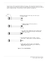
3.


Seal the antenna and gasket to the fuselage using a good quality electrical grade sealant.  Use caution to
ensure that the antenna connector is not contaminated with sealant.  Ensure that the mounting screws are
fully tightened and that the antenna base is well seated against the gasket.

CAUTION: Do not use construction grade RTV sealant or sealants containing acetic acid.  These

sealants may damage the electrical connections to the antenna.  Use of these types sealants
may void the antenna warranty.

Содержание GPS 155XL

Страница 1: ...36 1 167 7 21 0 18 Garmin International 1200 E 151st Street Olathe KS 66062 USA 190 00067 22 Rev E September 2000...

Страница 2: ...d and to print one copy of this manual or of any revision hereto provided that such electronic or printed copy of this manual or revision must contain the complete text of this copyright notice and pr...

Страница 3: ...ALONE Personnel shall not under any circumstances reach into or enter any enclosure for the purpose of servicing or adjusting the equipment without immediate presence or assistance of another person...

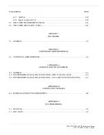
Страница 4: ...Only 1 3 1 3 LICENSE REQUIREMENTS 1 4 1 4 CERTIFICATION 1 4 1 4 1 German Certification 1 4 1 5 LIMITED WARRANTY 1 5 SECTION 2 INSTALLATION 2 1 INTRODUCTION 2 1 2 2 ANTENNA CONSIDERATIONS 2 1 2 2 1 GPS...

Страница 5: ...3 7 3 11 COMM ANTENNA INSTALLATION CHECK GNC 300XL 3 8 SECTION 4 POST INSTALLATION CONFIGURATION CHECKOUT PROCEDURE 4 1 INTRODUCTION 4 1 4 2 TEST MODE OPERATIONS 4 1 4 3 INSTALLATION CONFIGURATION 4...

Страница 6: ...SECTION 5 DIAGRAMS 5 1 GENERAL 5 1 SECTION 6 CONTINUED AIRWORTHINESS 6 1 CONTINUED AIRWORTHINESS 6 1 APPENDIX A CERTIFICATION DOCUMENTS A 1 GENERAL A 1 A 2 ENVIRONMENTAL QUALIFICATION FORM GPS 155XL G...

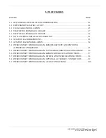
Страница 7: ...A INSTALLATION DRAWING 5 2 5 2 AVIATION RACK DIMENSIONS 5 3 5 3 AVIATION RACK INSTALLATION 5 4 5 4 INTERCONNECT WIRING DIAGRAM REMOTE BATTERY AND ENCODING ALTIMETER CONNECTIONS 5 5 5 5 INTERCONNECT WI...

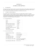
Страница 8: ...of aircraft to determine that the aircraft installation conditions are within the TSO standards The system may be installed only if evaluation by the applicant documents an acceptable installation an...

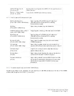
Страница 9: ...4 Output capable of driving devices as listed in Section 4 Conforms to the EIA specification RS 232C RS232 Chan 2 Output Data Pin 19 Output capable of driving devices as listed in Section 4 Conforms t...

Страница 10: ...to 470 ohm load Standard carbon or dynamic MIC containing transistorized pre amp Remote Transfer Pin 10 GNC 300XL Only Input when grounded swaps the active and standby COMM frequencies TX Interlock Pi...

Страница 11: ...e FCC requires GARMIN to inform users that these units meet the more stringent requirements For Home or Office Use The following guidance is provided to help ensure the proper licensing of the GNC 300...

Страница 12: ...THIS WARRANTY GIVES YOU SPECIFIC LEGAL RIGHTS WHICH MAY VARY FROM STATE TO STATE IN NO EVENT SHALL GARMIN BE LIABLE FOR ANY INCIDENTAL SPECIAL INDIRECT OR CONSEQUENTIAL DAMAGES WHETHER RESULTING FROM...

Страница 13: ...Antenna Location GNC 300XL The COMM antenna should be well removed from all projections engines and propellers The ground plane surface directly below the antenna should be a flat plane over as large...

Страница 14: ...of the GNC 300XL GPS antenna relative to a COMM and COMM antenna including its own is critical Figure 2 1 GPS Antenna Installation Considerations Use the following guidelines in addition to others in...

Страница 15: ...d the installer insures that the attenuation does not exceed 10 dB at 1 5 GHz for the specific installation Check that there is ample space for the cabling and mating connectors Avoid sharp bends in c...

Страница 16: ...To From information This can be displayed on the EFIS HSI or CDI External Annunciators and Switches NAV Annunciator GPS Annunciator NAV GPS Switch HOLD Annunciator AUTO Annunciator GPS Sequence Switch...

Страница 17: ...INPUT Pressure altitude input from an external source may be derived from a RS 232 compatible serial altitude input or Parallel Gray Code Gillham Altitude as described in Section 4 of this manual Gill...

Страница 18: ...010 10040 02 This kit contains the following items DESCRIPTION GPN QTY FLANGE MOUNT GA 56 ANTENNA SUB ASSEMBLY 011 00147 00 1 NUT PLATE 115 00080 00 1 SCREW 10 32 X 5 8 211 62212 14 4 ANTENNA GASKET...

Страница 19: ...XL P N 190 00067 20 Pilot s Guide GARMIN GNC 300XL P N 190 00067 30 3 2 DATA BASE OPTIONS DESCRIPTION GPN MEMORY CARD WORLDWIDE DATABASE 010 10051 00 MEMORY CARD AMERICAS DATABASE 010 10051 01 MEMORY...

Страница 20: ...ENNA INSTALLATION For the COMM antenna follow the manufacturer s instructions GNC 300XL The remainder of this section applies to the GPS antenna The GA 56 Antenna outline and footprint dimensions are...

Страница 21: ...tions for cable preparation 3 Contacts for the 37 and 26 pin connectors must be crimped into the individual wires of the aircraft wiring harness Table 3 1 lists contact part numbers for reference and...

Страница 22: ...Cannon P N 031 10007 001 Pin Contact ITT Cannon P N 330 5291 055 These contacts require the use of a different crimp tool positioner than shown in the table with the part numbers as follows Daniels P...

Страница 23: ...crews are inserted from the inside through the holes in the sides of the rack see Figure 5 3 3 9 GPS 155XL GNC 300XL INSTALLATION AND REMOVAL 1 The GPS 155XL GNC 300XL is installed in the rack by gent...

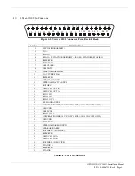
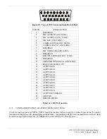
Страница 24: ...ACTV ANNUN 14 ROTOR C 15 ARINC 429 OUT B 16 ARINC 429 OUT A 17 RS232 IN 1 18 RS232 IN 2 19 RS232 OUT 2 20 MESSAGE ANNUN 21 AIRCRAFT POWER 14 VDC GNC 300XL 14 28 VDC GPS 155XL 22 GROUND 23 OBI SYNC 24...

Страница 25: ...15 ALTITUDE A1 16 ALTITUDE A2 17 ALTITUDE A4 18 ALTITUDE B1 19 ALTITUDE B2 20 ALTITUDE B4 21 ALTITUDE C1 22 ALTITUDE C2 23 ALTITUDE C4 24 ALTITUDE COMMON 25 GROUND 26 REMOTE ENTER Table 3 3 J102 Pin F...

Страница 26: ...first page displayed is the Display Test Page While in TEST MODE test pages can be selected by ensuring the flashing cursor is off and rotating the large knob in either direction To change data on th...

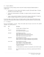
Страница 27: ...d P N 190 00067 30 for the GNC 300XL 4 3 2 I O Channel 1 Select the I O CHANNEL 1 Test Page Change the selectable input and output to match that of the installed equipment The available options are In...

Страница 28: ...GPS III 4 3 3 ARINC 429 Channel Select the ARINC 429 Channel Test Page Change the selectable output to match that of the installed equipment The available options are Input Field Description off No un...

Страница 29: ...titude 311 Present position longitude 312 Ground speed 313 Ground track 314 True heading 320 Magnetic heading 147 Magnetic variation 261 GPS navigation mode 275 Navigation status 326 Lateral scale fac...

Страница 30: ...remely accurate input source input 150 to the GPS 155XL GNC 300XL The input course will indicate close to 150 and a Calib field will appear in the lower right corner Selecting the Calib field will cal...

Страница 31: ...e NAV common Common long range NAV NOTE The strap option affects the interpretation of ARINC 429 input data For ARINC 429 input data the following applies Lnav 1 Only data with SDI 0 or SDI 1 is used...

Страница 32: ...GPS Corrections Message Type 3 Reference Station Parameters Message Type 9 High Rate Differential Corrections Output Field Description off No units connected to Channel 2 output plotting Serial positi...

Страница 33: ...ttery as follows Rmt Bat none if Remote Battery is selected as none on the Configuration Page Rmt Bat voltage mode auto status mode represents the mode of the charger and is selectable On enables the...

Страница 34: ...or OFF Ensure the Arrival Annunciator is OFF ON Ensure the Arrival Annunciator is ON Approach Annunciator OFF Ensure all Approach Annunciators are OFF ACTV Ensure the Approach Active Annunciator is ON...

Страница 35: ...BI Test Page Using the controls on the GPS 155XL GNC 300XL front panel make the selections indicated below and verify the interfaces as appropriate OBI Data VALID Ensure that the OBI indicates the pro...

Страница 36: ...f the NAV flag comes into view refer to Section 2 2 5 for options to improve performance 4 6 VHF COMM CHECK GNC 300XL A flight test is recommended after the installation is complete to ensure satisfac...

Страница 37: ...Aviation Rack Dimensions Figure 5 3 Aviation Rack Installation Figure 5 4 Interconnect Wiring Diagram Remote battery and Encoding Altimeter Connections Figure 5 5 Interconnect Wiring Diagram Navigati...

Страница 38: ...GPS 155XL GNC 300XL INSTALLATION MANUAL FIGURE 5 1 GA 56 ANTENNA INSTALLATION DRAWING 190 00067 22 REV E PAGE 5 2...

Страница 39: ...GPS 155XL GNC 300XL INSTALLATION MANUAL FIGURE 5 2 AVIATION RACK DIMENSIONS 190 00067 22 REV E PAGE 5 3...

Страница 40: ...GPS 155XL GNC 300XL INSTALLATION MANUAL FIGURE 5 3 AVIATION RACK INSTALLATION 190 00067 22 REV E PAGE 5 4...

Страница 41: ...GPS 155XL GNC 300 XL INSTALLATION MANUAL FIGURE 5 4 INTERCONNECT WIRING DIAGRAM REMOTE BATTERY AND ENCODING ALTIMETER CONNECTIONS 190 00067 22 REV E PAGE 5 5...

Страница 42: ...GPS 155XL GNC 300 XL INSTALLATION MANUAL FIGURE 5 5 INTERCONNECT WIRING DIAGRAM NAVIGATION INDICATOR CONNECTIONS 190 00067 22 REV E PAGE 5 6...

Страница 43: ...GPS 155XL GNC 300 XL INSTALLATION MANUAL FIGURE 5 6 INTERCONNECT WIRING DIAGRAM BENDIX KING KI 209A CONNECTIONS 190 00067 22 REV E PAGE 5 7...

Страница 44: ...GPS 155XL GNC 300 XL INSTALLATION MANUAL FIGURE 5 7 INTERCONNECT WIRING DIAGRAM SWITCH ANNUNCIATOR CONNECTIONS 190 00067 22 REV E PAGE 5 8...

Страница 45: ...GPS 155XL GNC 300 XL INSTALLATION MANUAL FIGURE 5 8 INTERCONNECT WIRING DIAGRAM OPTIONAL ACCESSORY CONNECTIONS 190 00067 22 REV E PAGE 5 9...

Страница 46: ...GPS 155XL GNC 300 XL INSTALLATION MANUAL FIGURE 5 9 INTERCONNECT WIRING DIAGRAM AUDIO CONNECTIONS 190 00067 22 REV E PAGE 5 10...

Страница 47: ...e used to indicate instances where explicit words should be substituted e g replace GPS 155XL GNC 300XL with GNC 300XL INSTRUCTIONS FOR CONTINUED AIRWORTHINESS GARMIN GPS 155XL GNC 300XL 1 Introductio...

Страница 48: ...nual 7 Removal and Replacement Information Refer to Section 3 paragraph 3 9 of this manual If the unit is removed and reinstalled a functional check of the equipment should be conducted in accordance...

Страница 49: ...ructions for Continued Airworthiness date ______ 17 Assistance Flight Standards Inspectors have the resources to respond to questions regarding the ICA 18 Implementation and Record Keeping For major a...

Страница 50: ...N 190 00067 22 Rev E Page A 1 APPENDIX A CERTIFICATION DOCUMENTS A 1 GENERAL This section contains the environmental qualification form for the GARMIN GPS 155XL GNC 300XL and GA 56 GPS Antenna The con...

Страница 51: ...ipment tested to Category A1 and D1 except as noted Low Temperature 4 5 1 High Temperature 4 5 2 4 5 3 In flight Loss of Cooling 4 5 4 Cooling air not required Altitude 4 6 1 Decompression 4 6 2 Overp...

Страница 52: ...RT NO 011 00134 00 Stud Mount 011 00147 00 Flange Mount TSO C129 Class A 1 MANUFACTURER S SPECIFICATION AND OR OTHER APPLICABLE SPECIFICATION 004 00015 00 MANUFACTURER GARMIN International ADDRESS 120...

Страница 53: ...st required Power Input 16 0 Equipment identified as Category X no test required Voltage Spike 17 0 Equipment identified as Category X no test required Audio Frequency Susceptibility 18 0 Equipment id...

Страница 54: ...ote battery connectors starting with serial numbers 33050055 Units with lower serial numbers have pin contacts on the battery pack Units 33050055 and up use socket contacts on the battery and the pin...

Страница 55: ...tent with N8110 69 or Order 8110 4 Aviation Authority approved installers are hereby granted permission to use STC SA00639WI data to modify aircraft C 2 GNC 300XL Consistent with N8110 69 or Order 811...

Страница 56: ...GPS 155XL GNC 300XL Installation Manual P N 190 00067 22 Rev E Page C 2...

Страница 57: ...GPS 155XL GNC 300XL Installation Manual P N 190 00067 22 Rev E Page C 3...

Отзывы: