Garmin G5 Electronic Flight Instrument Part 23 AML STC Installation Manual
190-01112-10
Rev. 21
Page 267
- LIGHTNING PROTECTION
F.1 Lightning Zones for GTP 59 and GMU11
This section provides lightning zoning diagrams for various types of aircraft to facilitate correct
placement of the GTP 59 and GMU11. Additional restrictions related to the placement of the GTP 59 can
be found in Section 4.1.7. Additional restrictions related to the placement of the GMU 11 can be found in
Section 4.1.3.
The zoning levels correspond to the severity of lightning strikes and probability of occurrence on the
aircraft. The order of severity starting with the safest zone is Zone 3, 2A, 2B, 1C, and 1A/1B. The GTP 59
cannot be installed in Zones 1A, 1B, 1C, or 2B.
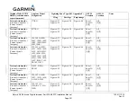
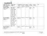
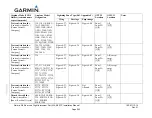
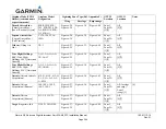
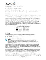
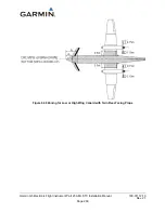
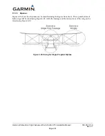
All diagrams in this appendix use the legend shown in Table 6-4. The zoning described is split into the
following: wings, fuselage, and empennage. For the particular airframe, the applicable wings, fuselage,
and empennage zoning should be merged to get a complete zonal definition. The zoning figures
applicable to any particular model are found in Table 6-3. If there is a region of overlapping zones, the
more severe zone should always be applied (i.e., if Zone 2A and 1A overlap in a region, then the
overlapping region should be considered Zone 1A). Examples of complete lightning zoning diagrams can
be found in Appendix Section F.2.
Table 6-4: Lightning Zoning Legend
F.1.1 Wings
The different zoning for wingtips and wings are contained in the following subsections.
F.1.1.1
Wingtips
F.1.1.1.1 Aircraft Not Limited to VFR Operation
NOTE
This zoning section is applicable to those aircraft models that are not limited to VFR
operation only in Table 6-3. For zoning of models limited to VFR operation only, refer to
Appendix Section F.1.1.1.2.
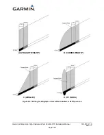
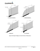
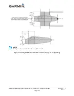
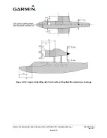
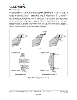
Zoning of various types of wingtips is shown in Figure 6-27. Figure 6-27A shows zoning for straight
wingtips. Figure 6-27B shows zoning for curved wingtips. The zones are similar to those of straight
wingtips. The main difference is that Zone 1 extends from the outboard edge of the wing past the tangent
point of the chord and 0.5 meters inboard.
Figure 6-27C shows zoning for winglets. Note that the winglet figure shows a flattened winglet. Winglet
classifications are very similar to those of curved wingtips. The main difference is that Zone 1 extends
from the outboard edge of the wing past the tangent point of the winglet and 0.5 meters inboard.
Figure 6-27D shows zoning for tip tanks. The rule that applies to tip tanks is very similar to that of the
curved wing. The main difference is that Zone 1 extends 0.5 meters past the inboard edge of the tip tank.

