background image


Garmin G5 Electronic Flight Instrument Part 23 AML STC Installation Manual 

190-01112-10 


Rev. 21 

Page 269 

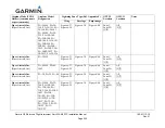
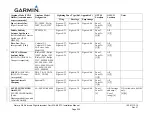
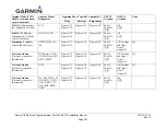
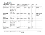
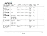
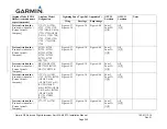
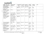
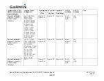
F.1.1.1.2  Aircraft Limited to VFR Operation 

This zoning section is applicable to those aircraft models that are limited to VFR operation only in 
APPENDIX E. For zoning of models that are not limited to VFR operation only, refer to 
Appendix Section F.1.1.1.1. 
 

NOTE 

The aircraft must have a position light in the wing tip area as a prerequisite for installing the 
GMU 11 or GTP 59. 
 

If there is no position light on the wing, then no Zone 3 exists and the GTP 59 cannot be installed on this 
particular aircraft. For those aircraft identified as VFR in Appendix D, the following criteria is used to 
determine the Zone 3 area: 


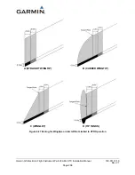
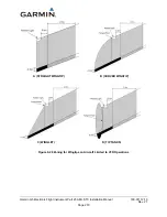
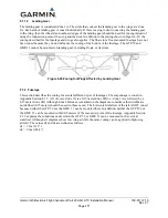
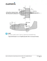
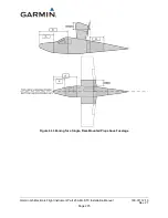
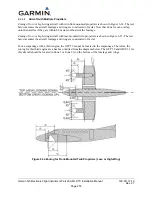
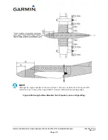
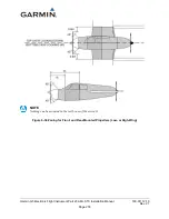
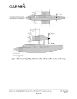
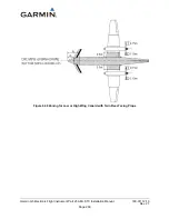
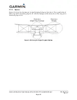
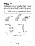
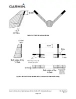
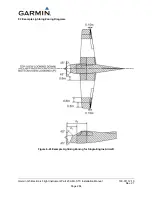
Zone 1A/1B finishes as shown in Figure 6-28 

or

 0.5 meters inboard from the inboard edge of the 

position light, whichever is the greater distance from the outboard edge of the wing tip, as shown 
in Figure 6-27 


Zone 2A/2B extends a total of 2.1 meters inboard of Zone 1A/1B 


Zone 3 extends inboard of Zone 2A/2B from the wing tip and stops at another Zone 1A/1B or 
2A/2B determined from other areas of Appendix Section F.1.2 


Содержание Approach G5 - GPS-Enabled Golf Handheld

Страница 1: ...190 01112 10 December 2019 Revision 21 Page 1 Garmin G5 Electronic Flight Instrument Part 23 AML STC Installation Manual ...

Страница 2: ...such electronic or printed copy of this manual or revision must contain the complete text of this copyright notice and provided further any unauthorized commercial distribution of this manual or any revision hereto is strictly prohibited Garmin flyGarmin are registered trademarks of Garmin International or its subsidiaries G5 trademark of Garmin International or its subsidiaries These trademarks m...

Страница 3: ...na Third Party autopilot model coverage and minor wiring typographical fixes 11 12 04 2017 Changed the configuration sections to match the changes from SW 5 00 and minor typographical fixes 12 02 27 2018 Updated Section 5 to add two single ADI interconnects and related configurations Removed wiring interface to GFC600 and minor typographical fixes Updated document to reflect G5 software version 5 ...

Страница 4: ...NS OF WARNINGS CAUTIONS AND NOTES WARNING This product its packaging and its components contain chemicals known to the State of California to cause cancer birth defects or reproductive harm This notice is being provided in accordance with California s Proposition 65 If you have any questions or would like additional information please refer to our web site at www garmin com prop65 WARNING Perchlor...

Страница 5: ...in dealer or the Garmin website Contact your local waste disposal department to dispose of the device and battery in accordance with applicable local laws and regulations CAUTION The display uses a lens with a special coating that may be sensitive to skin oils waxes and abrasive cleaners CLEANERS CONTAINING AMMONIA WILL HARM THE ANTI REFLECTIVE COATING It is very important to clean the lens using ...

Страница 6: ...lectrical Installation 81 4 3 Weight and Balance 89 4 4 Electrical Load Analysis 89 4 5 Electrical Bonding 98 5 SYSTEM INTERCONNECTS 106 5 1 G5 Interconnect Notes 107 5 2 Power and Ground 108 5 3 G5 ADI with a GPS Antenna 109 5 4 G5 ADI with GPS Position Input 111 5 5 G5 ADI and GMU 11 with GPS Position Input 115 5 6 G5 ADI or DG GMU 11 and GPS Antenna 119 5 7 G5 HSI with VHF Navigator 122 5 8 G5 ...

Страница 7: ...re 1 8 GTP 59 Temperature Probe 24 Figure 3 1 CAN Bus Backbone 33 Figure 3 2 Correct CAN Bus Wiring Example and Node Connections 33 Figure 3 3 Incorrect CAN Wiring Example 34 Figure 3 4 CAN Bus Termination 011 02887 00 for G5 GMU 11 and GAD 13 34 Figure 3 5 CAN Bus Termination for GAD 29 29B 35 Figure 3 6 CAN Bus Termination for G5 on M27500 Wire 35 Figure 3 7 GAD 29B Inline Transformer Mounting I...

Страница 8: ...l G5 Recessed Installation 56 Figure 4 22 Instrument Panel Limitations 57 Figure 4 23 Instrument Panel View Looking Forward 58 Figure 4 24 Instrument Panel View with Instruments Removed 58 Figure 4 25 Recessed Adapter Plate Located on Panel 59 Figure 4 26 Match Drilling Through Panel Using Adapter Plate as Template 59 Figure 4 27 Preliminary Trimming of Adapter Plate 60 Figure 4 28 Adapter Plate L...

Страница 9: ...Completed Electrical Load Tabulation Form Sheet 2 of 2 97 Figure 4 56 Nut and Washer Electrical Bonding 98 Figure 4 57 Nut Plate Electrical Bonding 98 Figure 4 58 Fiberglass Insulation for Carbon Fiber Material 100 Figure 4 59 Aluminum Tape Joint 100 Figure 4 60 Aluminum Tape Ground Termination 101 Figure 4 61 GAD 29 29B Aluminum Tape Installation GAD 13 similar 102 Figure 4 62 10 Terminal Install...

Страница 10: ...D 29B Interface to Cessna Autopilots Sheet 2 of 2 187 Figure 5 31 GAD 29B Interface to Honeywell Autopilots 188 Figure 5 32 GAD 29B Interface to S TEC Autopilots 190 Figure 5 33 GAD 29B Interface To Piper Autopilots 192 Figure 6 1 Attitude Calibration Example 200 Figure 6 2 Example of Calibration Equations 200 Figure 6 3 Engine Vibration Test Failure Indication 202 Figure 6 4 ADI display of OAT an...

Страница 11: ...d with a Rear Mounted Propeller 273 Figure 6 32 Zoning for a Low or High Wing Aircraft with a Curved Lower Fuselage 274 Figure 6 33 Zoning for a Single Rear Mounted Prop above Fuselage 275 Figure 6 34 Zoning for Front Mounted Twin Propellers Low or High Wing 276 Figure 6 35 Zoning for Rear Mounted Twin Propellers Low or High Wing 277 Figure 6 36 Zoning for Front and Rear Mounted Propellers Low or ...

Страница 12: ...bels 32 Table 4 1 GMU 11 Supporting Hardware 67 Table 4 2 GAD 29 29B GAD 13 Supporting Hardware 70 Table 4 3 Contact Crimp Tooling 81 Table 4 4 G5 1P51 2P51 GMU 11 P111 and GAD 13 P131 Connector Parts 83 Table 4 5 GAD 29 29B 9 pin P291 Connector Parts 84 Table 4 6 GAD 29 29B 25 pin P292 Connector Parts 85 Table 4 7 LRU Weights 89 Table 4 8 Sample Net Electrical Load Change Calculation 90 Table 4 9...

Страница 13: ...attitude indicator Alternatively for installations that do not install the G5 as a replacement primary attitude indicator the G5 can be installed as a second attitude indicator in place of the existing rate of turn indicator If the existing rate of turn indicator is interfaced with the autopilot it cannot be replaced by a G5 The G5 can only be installed in the locations specified in this STC It is...

Страница 14: ...ds Techniques and Practices Aircraft Alterations AC 43 13 2B Aerospace Systems Electrical Bonding and Grounding for Electromagnetic Compatibility and Safety SAE ARP1870 Standard Guide for Aircraft Electrical Load and Power Source Capacity Analysis ASTM F 2490 05 GTN 6XX 7XX Install Manual 190 01007 A3 GNS 400W Series Installation Manual 190 00356 08 GNS 500W Series Installation Manual 190 00357 08...

Страница 15: ...ometer 011 04349 01 010 01788 01 006 B2770 XX GMU 11 GMU 11 Installation Kit 011 04349 90 010 01788 01 N A GAD 29 Data Bus Converter 011 03236 01 010 01172 01 006 B1760 XX GAD 29B Data Bus Converter 011 03236 11 010 01172 11 006 B1760 XX GAD 29 29B GAD 29 29B Connector Kit 011 03271 00 N A N A GPS Antenna TNC Glareshield mount GPS antenna 011 04036 00 010 12444 00 N A TNC BNC Adapter Coax adapter ...

Страница 16: ...operation with up to 4 hours of emergency power Figure 1 1 G5 Electronic Flight Instrument Attitude 1 6 1 1 Attitude The G5 calculates aircraft attitude using information from its built in inertial sensors If the G5 senses that the attitude solution is valid but not yet within the internal accuracy limits ALIGNING is displayed The G5 can align itself both while taxiing and during level flight The ...

Страница 17: ...t is possible to connect to both a Glare Shield Mounted GPS Antenna via a coaxial cable and a GPS navigator over RS 232 simultaneously Additionally the G5 functions provided by the GPS are shown below Ground Track Ground Speed GS 1 6 1 5 Air Data The G5 unit is connected to the aircraft Pitot Static system and optionally connected to the GAD 13 for Outside Air Temperature OAT information See secti...

Страница 18: ...G 1 6 1 8 G5 Attitude Interface Summary The G5 Electronic Flight Instrument when configured as an attitude indicator in this STC installation uses 14VDC or 28 VDC power ground RS 232 CAN bus and coax connection for the Glare Shield Mounted GPS Antenna The following list is a summary of interfaces used by the G5 Attitude indicator Aircraft Power and Ground Aircraft Pitot Static GPS Coax connection ...

Страница 19: ...o allow heading information from the GMU 11 communication of navigation data from the GAD 29 29B communication between the G5 Attitude indicator and the G5 HSI and communication of Outside Air Temperature OAT information from the GAD 13 For specific wiring information refer to Section 5 1 6 2 G5 DG HSI Indicator The G5 Electronic Flight Instrument configured as an HSI is shown in Figure 1 3 The G5...

Страница 20: ...f the aircraft The G5 HSI will be used to input OBS Course information The G5 HSI can be used as a backup Attitude Airspeed Altitude Indicator If installed a G5 Attitude indicator can also present VHF NAV lateral and vertical deviation 1 6 2 3 G5 HSI GPS NAV For installations where the G5 HSI is being used for GPS NAV the G5 will be installed with a Garmin GPS navigator and the GAD 29 29B The G5 H...

Страница 21: ...teral and vertical For specific configuration settings for RS 232 refer to Section 5 If an existing connection is made to the RS 232 port the G5 connection can be spliced into the existing wiring at the connector For specific wiring information refer to Section 5 1 6 2 10 G5 DG HSI CAN Bus Interface Summary The G5 DG HSI can utilize CAN bus connections when specified by a specific equipment config...

Страница 22: ...tionality 2 Low Speed ARINC 429 Transmitters 4 Low Speed ARINC 429 Receivers 1 CAN Network Port Analog Outputs Excitation Pass Through GAD29B only For the G5 Attitude and or G5 DG HSI installation the GAD 29 29B will receive ARINC 429 data from the navigators interfaced and transmit that information onto the CAN bus to be consumed by the G5 The GAD 29 29B can run on 14VDC or 28VDC The GAD 29 29B c...

Страница 23: ... is installed as an ADI HSI or DG and not connected to a WAAS enabled GPS source the G5 must be connected to this antenna Figure 1 6 Glare Shield Mounted GPS Antenna 1 6 6 GAD 13 The GAD 13 is a small unit used to interface to OAT probes The GAD 13 provides a standard three wire or two wire interface that can be connected to the following approved OAT probes GTP 59 C307PS Davtron OAT analog inform...

Страница 24: ...12 10 Rev 21 Page 24 1 6 7 GTP 59 The Garmin GTP 59 is an externally mounted temperature probe that provides raw outside air temperature data The device is a three wire temperature probe interface with a pre installed wire lead that is 10 feet long Figure 1 8 GTP 59 Temperature Probe ...

Страница 25: ...are Shield Mounted GPS Antenna 2 88 in 0 60 in 2 22 in 0 20 lb N A GAD 13 1 43 in 0 78 in 1 91 in 0 14 lb 0 24 lb Depth behind aircraft panel Weight includes mounting ring Depth is width of antenna An 8 FT lead is pre installed with this antenna 1 7 2 Power Requirements Table 1 4 Power Requirements LRU Characteristics Specifications G5 Average Current Draw 14 VDC 200 A Max Current Draw 14 VDC 250 ...

Страница 26: ...installed in an aircraft with an electrical power generating system capable of supplying 14 VDC or 28 VDC if a G5 is being installed as an attitude indicator and an existing attitude indicator is retained the G5 pointer type must be configured to match the existing indicator pointer type o Fixed Pointer Type G5 Config Ground o Movable Pointer Type G5 Config Sky cannot replace a primary attitude in...

Страница 27: ...llation Table 3 1 Contents of the G5 Installation Kit 011 03892 00 Item Garmin P N Quantity Connector Kit 9 Pin w CAN Term 011 03002 00 1 Mounting Ring G5 115 02251 03 1 Screw 6 32 0 500 211 60207 12 3 NOTE Not all items included in kit P N 011 03002 00 are used in this installation The installation kit listed in Table 3 2 is required any time a GMU 11 is installed Table 3 2 Contents of the GMU 11...

Страница 28: ... Sckt 9 Place 330 00625 09 1 Contact Socket Military Crimp Size 20 336 00022 02 11 Contact Pin Military Crimp Size 20 336 00024 00 27 The item listed in Table 3 5 will be supplied when a G5 DG HSI is ordered The adapter plate is used whenever a G5 is installed and any instrument panel modification has taken place or a G5 is installed in an instrument hole with cutouts for instrument knobs Alternat...

Страница 29: ... 2 X or equivalent Silicone fusion tape A A 59163 MIL I 46852C or equivalent Environmental splice AS81824 1 X where X size or equivalent Flat braid 1 16 AA59569F36T0062 or equivalent Tubing and fittings are required to connect pitot and static air to the G5 Pitot and Static plumbing parts are aircraft specific see Section 4 1 5 120Ω CAN cable see section 3 4 5 for more information There are two op...

Страница 30: ...ng nut plates NAS1832 NAS1834 or NAS1836 potted inserts maybe required if honeycomb core panels are used to support the installation of G5 components Synthetic Fastener Tape A A 55126 used for mounting Glare Shield Mounted GPS Antenna 3 3 Test Equipment The following test equipment is required to complete the G5 installation and to perform post installation checkout of the system Ground power cart...

Страница 31: ...apter is required to connect this antenna to the G5 adapter P N 330 01754 00 3 4 2 Considerations for Vacuum System If a vacuum driven instrument is removed the vacuum source must be capped and the system checked for leaks See the aircraft specific maintenance manual for procedure The vacuum system and associated parts may be removed if there is no remaining need for vacuum See the aircraft specif...

Страница 32: ...0Ω CAN cable for the following scenarios If CAN bus lengths are expected to reach the maximum allowed see section 3 4 5 2 If there are future plans to install Garmin STC s SA01866WI Installation of Garmin GFC 500 Autopilot with Electronic Stability and Protection or SA01899WI Installation of Garmin G3X Touch Electronic Flight Instrument System If none of the above mentioned scenarios are a factor ...

Страница 33: ...lso known as the CAN bus CAN was developed by Bosch GmbH in the 1980s and its specifications are currently governed by ISO 11898 2 CAN is widely used in aviation automotive and industrial applications due to its simplicity and reliability 3 4 5 2 1 CAN Bus Architecture The electrical architecture of the CAN bus takes the form of a linear backbone consisting of a single twisted wire pair with an LR...

Страница 34: ...or backshells on all devices connected to the CAN bus 3 4 5 2 3 CAN Bus Termination At each of the two extreme ends of the CAN bus backbone a 120Ω resistor is installed to terminate the bus Termination resistors are provided either via termination adapters that plug into an LRU s CAN connection a resistor internal to the LRU or a 120Ω resistor installed into the wiring harness at a G5 if the G5 is...

Страница 35: ...logies and do not use a hub device see Figure 3 3 The overall length of the bus should not exceed 85 feet Do not connect more than one device to the CAN bus backbone at the same point Instead daisy chain the CAN bus backbone from one device to the next Observe proper wiring shielding and grounding requirements as described above Terminate the CAN bus at the two extreme ends of the bus as described...

Страница 36: ...0 For shield terminations at the GPS or VHF Navigator follow the appropriate installation techniques as indicated by the manufacturers installation instructions for that unit If there are any interposing connectors then the shields must have continuity through the interposing connector This can be achieved by 1 Terminating the shields to the backshell of the connector if both mating connectors and...

Страница 37: ...tor installations utilizing 120Ω CAN cable and shielded twisted pair cable MIL C 27500 installations that do not use the G5 as a CAN bus terminator see Figure 3 8 and Figure 3 9 Method B should be used for resistor installations that use the G5 as a terminator and are utilizing shielded twisted pair cable MIL C 27500 see Figure 3 10 and Figure 3 11 Figure 3 8 and Figure 3 13 show the buildup and i...

Страница 38: ... Solder component to wire per SAE AS4461 Note Acceptable solder types are SN60 or SN63 Clean Flux residues using an appropriate flux cleaner 2 Cover component and at least 0 5 inch of wire on each side of component leads with heatshrink as shown above Shrink in place Note 1 Use heatshrink M23053 5 104 Y for the diode use M23053 5 106 Y for the resistor The Y character is for color of heatshrink co...

Страница 39: ...Garmin G5 Electronic Flight Instrument Part 23 AML STC Installation Manual 190 01112 10 Rev 21 Page 39 Figure 3 9 Method A Placement of G5 CAN Bus Resistors ...

Страница 40: ...e Section 5 for complete wiring interconnect details Figure 3 10 Method B G5 Resistor Preparation Steps for component installation 1 Solder resistor to at least 1 of stranded M22759 wire per SAE AS4461 Note Acceptable solder types are SN60 or SN63 Clean flux residues using an appropriate flux cleaner 2 Cover component and at least 0 5 of wire on each side of component leads with heatshrink as show...

Страница 41: ...0 2 Solder resistor buildups together as shown in the above figure per AS4461 A simplified circuit is shown below Note Acceptable solder types are SN60 or SN63 Clean flux residues using an appropriate flux cleaner Figure 3 12 Wire P N M27500 Simplified Resistor connections 3 Secure the resistors together in the wire bundle as shown above Note The Z character in the cable tie P N is for color color...

Страница 42: ...n Both Wire types Figure 3 8 shows the installation procedure for the diode into the wiring harness For part numbers of diode see Section 3 2 1 Figure 3 13 shows the placement of the diode on each power input for the G5 See Section 5 for complete wiring interconnect details Figure 3 13 Placement of G5 Power Diode Bothe Wire Types ...

Страница 43: ... It is important that the G5 is installed perpendicular to the aircraft s longitudinal axis display bezel parallel to the wing spar carry thru and as close to level in the roll axis as possible Small roll offsets and pitch offsets up to 15 can be corrected for during calibration In addition to the installation limitations in Section 2 1 consider the following when selecting a mounting location for...

Страница 44: ...below the instrument in the top center position when possible 4 1 2 1 Mounting Ring Installation The G5 Mounting Ring 115 02251 03 can be used as a template when marking the panel for cutout For complete cutout dimensions see Figure 6 15 Secure the mounting ring to the aircraft panel using the supplied 6 32 pan head Phillips mounting screws Evenly torque the mounting screws to 10 12 in lbs The G5 ...

Страница 45: ...Garmin G5 Electronic Flight Instrument Part 23 AML STC Installation Manual 190 01112 10 Rev 21 Page 45 Figure 4 2 G5 Mounting Ring Figure 4 3 Maximum Misalignment of the G5 in the Lateral Axis ...

Страница 46: ...ronic Flight Instrument Part 23 AML STC Installation Manual 190 01112 10 Rev 21 Page 46 Figure 4 4 Maximum Misalignment of the G5 in the Longitudinal Axis Figure 4 5 Maximum Misalignment of the G5 in the Vertical Axis ...

Страница 47: ...n the mounting ring pushing the unit flush with the instrument panel and fastening the captive 3 32 hex socket head screw to the mounting ring as shown in Figure 4 6 To fasten the captive screw to the mounting ring insert a 3 32 hex drive tool through the access hole in the front cover of the G5 as shown in Figure 4 7 Torque the captive mounting screw to 10 12 in lbs Figure 4 6 G5 Alignment Pin Fi...

Страница 48: ...995 To replace the screw remove the two 4 40 flat head Phillips mount plate screws the G5 screw mount plate and the captive screw as shown in Figure 4 8 Reverse this process to install the longer 6 32 hex socket head screw Ensure correct orientation of the screw mount plate before applying 6 8 in lb of torque to the 4 40 mount plate screws NOTE Standard 6 32 hex socket head screws use a 7 64 hex d...

Страница 49: ...ches center to center Some instrument panels may require modification of existing holes to gain the needed 3 6 inch spacing Figure 4 9 Required Vertical Spacing Between G5 Units The panel may be modified by enlarging one hole or both up to a maximum of 0 25 inch per instrument hole The proposed positions must be such that neither G5 unit is obscured by the glareshield control yoke or other object ...

Страница 50: ...when any instrument panel modification has taken place G5 is installed in an instrument hole with cutouts for instrument knobs The G5 adapter plate is fabricated from 0 050 thick 2024 T3 aluminum per the dimensions shown in Figure 4 11 Apply a finish coat of paint to adaptor plates as desired prior to final installation These may be field fabricated if needed and must have some type of corrosion p...

Страница 51: ...nches thick 3 The dimensions and limitations of the hole must be as shown in Figure 4 13 4 The new location must satisfy the alignment requirements shown in Figure 4 3 Figure 4 4 and Figure 4 5 5 There must be at least 0 25 inches between the main instrument hole or the screw holes and any adjacent holes or the edges of the panel 6 The instrument panel must be structurally capable of supporting th...

Страница 52: ...e instrument panel which positions the display flush with the instrument panel A full understanding of this modification is required before starting A recessed adapter plate and modification of the instrument panel will be needed Some instrument panels may not be capable of supporting this modification See section 4 1 2 6 5 for suggested adapter plate modification procedure Figure 4 15 Recessed Ad...

Страница 53: ... holes and can be used as a template for creating the recessed cutout Figure 4 16 Recessed Adapter Plate Template Reference Holes 4 1 2 6 1 Recess Mounting Single G5 Install a single recessed G5 as illustrated by Figure 4 17 and Figure 4 18 A G5 installation in the attitude position is shown but the same instructions can be used when installing a G5 in the DG or turn coordinator positions Modify 1...

Страница 54: ...c Flight Instrument Part 23 AML STC Installation Manual 190 01112 10 Rev 21 Page 54 Figure 4 17 Single G5 Recessed Adapter Plate Installation Install G5 unit per section 4 1 2 2 Figure 4 18 Single G5 Recessed Installation ...

Страница 55: ...al recessed G5s as illustrated by Figure 4 19 and Figure 4 20 A minimum of six No 6 MS35206 2XX screws must be used to secure the modified mounting adapter plate in place Maintain 1 5D edge distance minimum Figure 4 19 Dual Vertical G5 Recessed Adapter Plate Installation Install G5 units per section 4 1 2 2 Figure 4 20 Dual Vertical G5 Recessed Installation ...

Страница 56: ...ntally in a similar manner to the dual vertical recessed installation A horizontal recessed adapter plate will need to be field fabricated in order to fit the existing installation This plate must be fabricated of 0 090 thick 2024 T3 aluminum and must have some type of corrosion protection primer alodine etc A minimum of six No 6 MS35206 2XX screws must be used to secure the modified mounting adap...

Страница 57: ...14 3 The hole must meet the limitations and minimums as shown in Figure 4 22 4 The modification must be completed in accordance with AC 43 13 2B Chapter 2 Any modification of subsequent structure or parts other than the instrument panel as defined in these instructions are beyond the scope of this manual Additional data from the aircraft manufacturer or other FAA approved data would be required fo...

Страница 58: ...3 AML STC Installation Manual 190 01112 10 Rev 21 Page 58 Figure 4 23 Instrument Panel View Looking Forward Figure 4 24 Instrument Panel View with Instruments Removed Temporarily remove instruments adjacent to proposed G5 location and or as needed ...

Страница 59: ...ocated on Panel Place 115 02733 00 Recessed Adapter Plate at desired location keeping in mind distance to instrument panel frame and other instruments Figure 4 26 Match Drilling Through Panel Using Adapter Plate as Template When ready mark adapter plate and match drill instrument panel 4x 098 diameter through adapter plate reference holes ...

Страница 60: ... AML STC Installation Manual 190 01112 10 Rev 21 Page 60 Figure 4 27 Preliminary Trimming of Adapter Plate Figure 4 28 Adapter Plate Located on Far Side of Instrument Panel Use reference holes from adapter plate to align adapter plate behind panel ...

Страница 61: ... 4 29 Additional Trimming of Adapter Plate Required Mark adapter plate where trimming is needed in order to avoid interference with any adjacent instrument or other item Figure 4 30 Trimmed Adapter Plate Trim adapter plate as needed remove only enough material to allow adapter plate to fit without interference ...

Страница 62: ...ion Manual 190 01112 10 Rev 21 Page 62 Figure 4 31 Adapter Plate Mounting Holes Drill 6 mounting holes through both adapter plate and panel maintain minimum 1 5D edge distance for No 6 hardware Figure 4 32 Dual G5 Panel Cutout Using Match Drilled Holes for Reference ...

Страница 63: ...on Manual 190 01112 10 Rev 21 Page 63 Figure 4 33 Instrument Panel After Cutout for Dual Vertical G5 Units Figure 4 34 Adapter Plate Installed Deburr and finish instrument panel and adapter plate as needed then install adapter plate per Section 4 1 2 6 1 or 4 1 2 6 2 ...

Страница 64: ... G5 Electronic Flight Instrument Part 23 AML STC Installation Manual 190 01112 10 Rev 21 Page 64 Figure 4 35 Dual Vertical G5 Units Installed Install G5 units per Section 4 1 2 2 This area intentionally blank ...

Страница 65: ...re 4 36 G5 Flush Mount Adapter Plate Printable Template The figure above may be photocopied and scaled as needed to match the full size part This paper copy may be used along with the instructions on Section 4 1 2 6 5 to verify the proposed installation of the G5 units will meet the installation requirements ...

Страница 66: ...aircraft is placed on jacks while leveled to avoid inadvertently placing the aircraft in a non level position when entering exiting or working the aircraft The GMU 11 should be mounted to a surface known to have sufficient structural integrity to withstand additional inertial forces imposed by the 0 26 pound unit In order to satisfy the structural mounting requirements for the GMU 11 the following...

Страница 67: ...2R 6 32 Stainless Steel Nuts MS21044C06 6 32 Stainless Steel In general wing mounting of the GMU 11 magnetometer is preferred Fuselage mounting is permitted but NOT within two feet of the cabin area because of numerous potential disturbances that can interfere with accurate operation The GMU 11 must be mounted in a serviceable location in the aircraft e g accessible through an access panel The GMU...

Страница 68: ...ng orientation as described in Figure 4 37 and Figure 4 38 2 Secure in place using tape if needed Do not use clamps or other devices that are ferrous or magnetic 3 Run the magnetic interference survey in accordance with APPENDIX C If the survey passes the location is considered reliable for the installation of the GMU 11 If the test fails the location should be considered unreliable until the sour...

Страница 69: ...g flange or break the screws Fasteners should be tightened until snug plus one quarter turn GMU should not be mounted in a composite wing It may be mounted in a wing constructed of metal so long as any hardware used to attach the GMU or its bracket do not penetrate the fuel tank For installation in a composite wing tip of a metal wing see APPENDIX D Use the hardware called out in Figure 4 39 to mo...

Страница 70: ...ting honeycomb core sandwich panels with aluminum face sheets are adequate and do not require additional reinforcement 4 A minimum of 3 between the GAD 29 29B and GAD 13 connector end and any object must be maintained to ensure clearance for connectors and wire harness 5 If a support bracket or shelf needs to be fabricated it should be fabricated and attached to the aircraft structure in accordanc...

Страница 71: ... Rev 21 Page 71 Screws MS35206 XXX OR AN525832RXX 8 Length A R Washers NAS1149FN8XXP OR 8 Nutplates Standard Part Any MS Mil Spec Part Number Nuts MS21044N08 Rivets MS20426AD3 X Countersunk Screws 8 MS24693 XXX Washers NAS1149FN832P Nuts MS21044N08 Figure 4 40 GAD 29 29B Mounting Hardware ...

Страница 72: ...9FN632P Nuts MS21044N06 Figure 4 41 GAD 13 Mounting Hardware 4 1 4 1 GAD 29B Transformer Mounting Instructions Reference Section 3 4 10 for GAD 29B transformer mounting 4 1 5 Pneumatic Connections The G5 Attitude indicator and G5 DG HSI use pitot and static pressure for the secondary display of altitude and airspeed The installer must install the necessary hoses and fittings to interface to the ex...

Страница 73: ... of the pneumatic plumbing lines to avoid moisture or debris collecting at or near the unit Ensure that no deformations of the airframe surface have been made that would affect the relationship between static air pressure and true ambient static air pressure for any flight condition Refer to 14 CFR Part 43 Appendix E and AC43 13 1B Chapter 12 Section 4 for approved practices while installing hoses...

Страница 74: ... has a low profile The optimal antenna position is horizontal or as close to horizontal as practical given the shape of the glareshield Fastener holes for screw mounted antenna installation as depicted in Figure 4 43 must not penetrate through the ventilation or defrost channels built into the glareshield if present If the glareshield is part of the instrument panel structure fastener holes may on...

Страница 75: ...Garmin G5 Electronic Flight Instrument Part 23 AML STC Installation Manual 190 01112 10 Rev 21 Page 75 Figure 4 43 Glare Shield Mounted GPS Antenna Screw mounted Installation Example ...

Страница 76: ...tes on the probe which in turn may affect computations of true airspeed delta ISA or other data that depends on the measurement of air temperature The GTP 59 cannot be mounted on or near a control surface Control surfaces include but are not limited to ailerons elevators rudder trim tabs and speed brakes GTP 59 Probe Installation in Metal and Tube and Fabric Aircraft For metal and tube and fabric ...

Страница 77: ...e access panel is less than 0 032 inch thick aluminum a doubler that is at least 0 032 inch thick aluminum per Figure 4 46 must be installed GTP 59 Probe Installation in Metallic Airframes For aircraft with metallic airframes a doubler is required when the GTP 59 probe is installed in the skin The doubler must be a minimum of 2 inches in diameter with a minimum thickness of 0 032 inches and at lea...

Страница 78: ...TP 59 Probe Installation in Composite Aircraft For composite aircraft the GTP 59 probe cannot be mounted on the fuselage and must be mounted on an access panel or inspection cover in a zone 3 area of the aircraft per APPENDIX F If the access panel or inspection cover is conductive a non conductive doubler must be used and a minimum 0 5 inches of clearance maintained between the GTP 59 probe termin...

Страница 79: ...cific information regarding acceptable lightning zones for the GTP 59 refer to APPENDIX E Refer to APPENDIX F for lightning zone details Regardless of location the probe must protrude into the air flow when the aircraft is in flight and be kept away from direct sources of heat e g engine exhaust direct sunlight cabin exhaust etc to provide an accurate air temperature measurement Figure 4 47 GTP 59...

Страница 80: ...Garmin G5 Electronic Flight Instrument Part 23 AML STC Installation Manual 190 01112 10 Rev 21 Page 80 Figure 4 48 GTP 59 Mounting Composite Aircraft Conductive Access Panel ...

Страница 81: ...mp tools and positioners are required to ensure consistent reliable crimp contact connections for the D sub connectors The following crimp tools are recommended Table 4 3 Contact Crimp Tooling Manufacturer Crimp Tool P N Positioner P N Insertion Extraction Tool P N MIL Spec M22520 2 01 M22520 2 08 M81969 1 02 Daniels AFM8 K13 1 4 2 2 Power Distribution The circuit protection device for the G5 and ...

Страница 82: ...onnector by gently tugging on the wire Mark harness connectors in accordance with AC 43 13 Chapter 11 Section 17 Route and secure the wiring harness away from sources of electrical interference The tables below list the parts required to complete the assembly of the G5 GMU 11 GAD 29 29B and GAD 13 wiring harness connectors Some of the parts required for this installation are included in the connec...

Страница 83: ... 7 Clamp Backshell Jackscrew 9 15 Pin 115 01078 00 2 8 Screw 4 40x 375 PHP SS P w Nylon 211 60234 10 2 9 Cover Backshell Jackscrew 9 15 Pin 115 01079 00 2 10 Screw 4 40x 187 FLHP100 SS P w Nylon 211 63234 06 2 11 Screw PHP 8 32 x 0 312 Cad Plated Steel or Screw PHP 8 32 x 0 312 Stainless MS35206 242 or MS51957 42 12 Split Washer 8 0 045 compressed thickness Cad plated Steel or Split Washer 8 0 045...

Страница 84: ... Backshell Jackscrew 9 15 Pin 115 01078 00 2 8 Screw 4 40x 375 PHP SS P w Nylon 211 60234 10 2 9 Cover Backshell Jackscrew 9 15 Pin 115 01079 00 2 10 Screw 4 40x 187 FLHP100 SS P w Nylon 211 63234 06 2 11 Screw PHP 8 32 x 0 312 Cad Plated Steel or Screw PHP 8 32 x 0 312 Stainless MS35206 242 or MS51957 42 12 Split Washer 8 0 045 compressed thickness Cad plated Steel or Split Washer 8 0 045 compres...

Страница 85: ...Backshell Jackscrew 25 44 Pin 115 01078 02 2 8 Screw 4 40x 375 PHP SS P w Nylon 211 60234 10 2 9 Cover Backshell Jackscrew 25 44 Pin 115 01079 02 2 10 Screw 4 40x 187 FLHP100 SS P w Nylon 211 63234 06 2 11 Screw PHP 8 32 x 0 312 Cad Plated Steel or Screw PHP 8 32 x 0 312 Stainless MS35206 242 or MS51957 42 12 Split Washer 8 0 045 compressed thickness Cad plated Steel or Split Washer 8 0 045 compre...

Страница 86: ...Garmin G5 Electronic Flight Instrument Part 23 AML STC Installation Manual 190 01112 10 Rev 21 Page 86 Figure 4 49 Wiring Harness Connector Assembly This area intentionally blank ...

Страница 87: ... in Figure 4 50 Keep the shield drains as short as practical 3 max total length See Table 4 4 Table 4 5 and Table 4 6 regarding numbers in parentheses in the following procedure 1 Strip 2 5 inches maximum 2 0 inches maximum for 9 pin connectors of the jacket to expose the shield braid 2 Remove the exposed braid 3 Carefully score the jacket 1 4 to 5 16 inches and remove the jacket to leave the brai...

Страница 88: ...l 6 will contact the wiring harness 12 Attach the strain relief clamp 7 to the connector backshell 6 using the supplied screws 8 CAUTION Placing the concave side of the strain relief clamp across the wiring harness will damage the wiring harness NOTE Only two ring terminals should be attached to each screw on the connector backshell shield ground It is preferred that only two wires be terminated i...

Страница 89: ...etermined the modification results in an increase in electrical load then it must be verified the electrical generation and reserve battery capacity remain adequate to support electrical loads essential to safe flight and landing of the aircraft 4 4 1 Aircraft with Existing Electrical Load Analysis If there is an existing electrical load analysis for the aircraft it must be updated to reflect the ...

Страница 90: ...ystem was within all limits prior to the G5 GMU 11 GAD 29 29B or GAD 13 installation Record the new electrical load calculations Table 4 8 Sample Net Electrical Load Change Calculation Items removed from aircraft Electrical Load Amps 1 SUBTOTAL Items added to aircraft G5 14 V typical 1 200 A 28 V typical 1 100 A GMU 11 14 V typical 1 100 A 28 V typical 1 100 A GAD 29 29B 14 V typical 1 200 A 28 V ...

Страница 91: ...d normal operation the primary electrical power generating system is operating normally emergency operation the primary electrical power generating system is inoperative and a back up electrical power generating system is being used This typically requires load shedding of non essential equipment to provide adequate electrical power to essential required equipment for safe flight and landing of th...

Страница 92: ...ng the expected load Figure 4 51 Ammeter Placement for Current Measurements 7 Ensure all circuit breakers are closed 8 Apply external power to the aircraft The voltage of the power source should be set to the nominal alternator voltage usually 13 8 VDC or 27 5 VDC 9 Turn on the battery master switch NOTE Intermittent electrical loads are not measured It is assumed if additional current is required...

Страница 93: ...13 Engage the autopilot if installed 14 Using the tabulation completed above switch on all continuous electrical loads which are used for the normal cruise phase and record the current measured by the ammeter measurement c in Figure 4 52 15 Using the tabulation completed above switch on all continuous electrical loads used for the emergency cruise phase and record the current measured by the ammet...

Страница 94: ...Garmin G5 Electronic Flight Instrument Part 23 AML STC Installation Manual 190 01112 10 Rev 21 Page 94 Figure 4 52 Blank Electrical Load Tabulation Form Sheet 1 of 2 ...

Страница 95: ...Garmin G5 Electronic Flight Instrument Part 23 AML STC Installation Manual 190 01112 10 Rev 21 Page 95 Figure 4 53 Blank Electrical Load Tabulation Form Sheet 2 of 2 ...

Страница 96: ...Garmin G5 Electronic Flight Instrument Part 23 AML STC Installation Manual 190 01112 10 Rev 21 Page 96 Figure 4 54 Sample Completed Electrical Load Tabulation Form Sheet 1 of 2 ...

Страница 97: ...Garmin G5 Electronic Flight Instrument Part 23 AML STC Installation Manual 190 01112 10 Rev 21 Page 97 Figure 4 55 Sample Completed Electrical Load Tabulation Form Sheet 2 of 2 ...

Страница 98: ...he head of the bolt or the washer if used under the head If primer or film was removed to achieve this then any exposed area still visible after the bond is completed must be refinished with the original finish or other suitable film e g primer or coating ref ARP1870 If the bolt is secured with washer and nut then a similar burnish area as described above shall occur between the washer and the mou...

Страница 99: ...of a bonding jumper Ensure that the installed bonding jumper meets the following specifications 1 The braid is a 7 16 or wider tubular braid part number QQB575R30T437 24 120 circular mils or a 3 4 or wider flat braid part number QQB575F36T781 20 800 circular mils 2 The braid contains a terminal lug mil spec MS20659 130 at each end 3 The strap length is as short as possible not exceeding 6 inches E...

Страница 100: ...length to width ratio b The bond strap shall be one inch wide and no longer than five inches 5 Prepare the aluminum surface at the ground location outlined in Section 4 5 3 or identify a ground stud to which the braid can be attached Any new ground stud shall also be prepared for electrical bonding 6 Route the tape between the LRU mount and the grounding location for the instrument panel If needed...

Страница 101: ...bonding strap is used The bonding strap shall be one inch wide and no longer than five inches Refer to Figure 4 60 12 Terminate both ends of the bonding strap with MS20659 130 terminal lugs 13 Install AN960C10 washer between the terminal lug and the mating metal surface and secure with a 10 steel bolt Ensure that the lug and washer are centered and in full contact with the mating surface with no o...

Страница 102: ...at grounding location 6 After the bond is complete if any films or coatings were removed from the surface reapply a suitable film or coating to the surrounding area 4 5 4 Bonding Strap for G5 and GMU 11 A bonding strap is required for the G5 A bonding strap is optionally required for a GMU 11 mounted in a non metallic wingtip see APPENDIX D for specific requirements and is required for a GMU 11 mo...

Страница 103: ... a LRU backshell Create the bonding strap using the following instructions 1 Cut an appropriate length of a metal braid listed in the table maximum 10 inches 2 Terminate both ends with the stated MS25036 terminal 3 Find a location on structure to create or re use an existing ground stud that is size 10 for connection to this bonding strap from the LRU backshell 4 If creating a new ground stud crea...

Страница 104: ...Garmin G5 Electronic Flight Instrument Part 23 AML STC Installation Manual 190 01112 10 Rev 21 Page 104 Figure 4 62 10 Terminal Installation on Garmin Backshell ...

Страница 105: ...ew ground studs for equipment grounding may be required for the G5 installation See Figure 4 63 for the parts required and the buildup sequence for ground stud installation Clean and prepare one side of the sheet metal surface in accordance with section 4 5 Figure 4 63 Pan Head Screw Ground Stud Buildup This area intentionally blank ...

Страница 106: ...ach installation and is only shown in Figure 5 2 NOTE The configuration tables are presented in order as the configuration pages on the G5 are presented To make configuration of the G5 easier configure the ARINC 429 and or RS 232 options first This allows for hidden configurations that require the ARINC 429 or RS 232 options to be selected as appropriate NOTE For the interconnects diagramed in thi...

Страница 107: ...Garmin G5 Electronic Flight Instrument Part 23 AML STC Installation Manual 190 01112 10 Rev 21 Page 107 5 1 G5 Interconnect Notes Figure 5 1 G5 Interconnect Notes ...

Страница 108: ...3 AML STC Installation Manual 190 01112 10 Rev 21 Page 108 CAUTION Check wiring connections for errors before connecting the wiring harness to the LRUs Incorrect wiring could cause component damage 5 2 Power and Ground Figure 5 2 Power and Ground ...

Страница 109: ...tter Enabled Air Data Air Data Sensors Enabled Vertical Speed Indicator 1 2 Airspeed Note Configure Units prior to setting airspeeds VNE 1 2 3 VNO 1 2 3 VSO 1 2 3 VS1 1 2 3 VFE 1 2 3 VA 1 2 3 VX 1 2 3 VY 1 2 3 VG 1 2 3 VR 1 2 3 VMC 1 2 3 VYSE 1 2 3 Magnetometer Magnetometer Disabled Flight Controls Garmin Autopilot Servos None Analog Autopilot Interface None Backlight Current Mode Automatic Defaul...

Страница 110: ...ut Format None ARINC 429 Output 1 None Output 2 None Input 1 None Input 2 None Input 3 None Input 4 None Exit Configuration Mode Note 1 Set configuration values and units to match the values indicated in the appropriate AFM and document settings in the space provided Note 2 If the aircraft has no AFM set the values as determined by the existing placards instrument bugs or instrument markings Note ...

Страница 111: ...Garmin G5 Electronic Flight Instrument Part 23 AML STC Installation Manual 190 01112 10 Rev 21 Page 111 5 4 G5 ADI with GPS Position Input Figure 5 4 G5 ADI with GPS Position Input ...

Страница 112: ...O 1 2 3 VS1 1 2 3 VFE 1 2 3 VA 1 2 3 VX 1 2 3 VY 1 2 3 VG 1 2 3 VR 1 2 3 VMC 1 2 3 VYSE 1 2 3 Magnetometer Magnetometer Disabled Flight Controls Garmin Autopilot Servos None Analog Autopilot Interface None Backlight Current Mode Automatic Default Mode Automatic Minimum Photocell Input Default Minimum Display Brightness Default Maximum Photocell Input Default Maximum Display Brightness Default Filt...

Страница 113: ...age RS 232 x x represents any available RS 232 Channel Input OFF Output MapMX 5 4 4 GNS 480 Configuration Config Page Config Option Configuration Setting GND Maint Serial Setup CH x x represents any available Serial Channel Output MapMX 5 4 5 GTX 3X5 Configuration Config Page Config Option Configuration Setting Interface Group RS 232 x x represents any available RS 232 Channel Output MapMX 5 4 6 G...

Страница 114: ...in the appropriate AFM and document settings in the space provided Note 2 If the aircraft has no AFM set the values as determined by the existing placards instrument bugs or instrument markings Note 3 Existing placards related to airspeed limitations must be retained Note 4 Setting can remain at default setting not supported in this configuration This area intentionally blank ...

Страница 115: ...Garmin G5 Electronic Flight Instrument Part 23 AML STC Installation Manual 190 01112 10 Rev 21 Page 115 5 5 G5 ADI and GMU 11 with GPS Position Input Figure 5 5 G5 ADI and GMU 11 with GPS Position Input ...

Страница 116: ... 3 VNO 1 2 3 VSO 1 2 3 VS1 1 2 3 VFE 1 2 3 VA 1 2 3 VX 1 2 3 VY 1 2 3 VG 1 2 3 VR 1 2 3 VMC 1 2 3 VYSE 1 2 3 Magnetometer Magnetometer Enabled Orientation Connector Aft Or Connector Forward Or Connector Port Or Connector Starboard Flight Controls Garmin Autopilot Servos None Analog Autopilot Interface None Backlight Current Mode Automatic Default Mode Automatic Minimum Photocell Input Default Mini...

Страница 117: ...y available RS 232 Port Output MapMX Format 1 5 5 3 GNS 4XXW 5XXW Configuration Config Page Config Option Configuration Setting MAIN RS232 CONFIG Page RS 232 x x represents any available RS 232 Channel Input OFF Output MapMX 5 5 4 GNS 480 Configuration Config Page Config Option Configuration Setting GND Maint Serial Setup CH x x represents any available Serial Channel Output MapMX 5 5 5 GTX 3X5 Co...

Страница 118: ...1 Note 1 Set configuration values and units to match the values indicated in the appropriate AFM and document settings in the space provided Note 2 If the aircraft has no AFM set the values as determined by the existing placards instrument bugs or instrument markings Note 3 Existing placards related to airspeed limitations must be retained Note 4 Setting can remain at default setting not supported...

Страница 119: ...G GMU 11 and GPS Antenna 5 6 1 ADI or DG Configuration Config Page Config Option Configuration Setting Device Information Installation Type Certified Instrument Diagnostics Data Log Enabled Attitude Configuration Indicator Type Normal Pitch Display Normal Roll Display For Fixed Type Pointers G5 Config Ground Pointer or For Movable Type Pointers G5 Config Sky Pointer ...

Страница 120: ...3 if a Non Garmin Autopilot is interfaced Backlight Current Mode Automatic Default Mode Automatic Minimum Photocell Input Default Minimum Display Brightness Default Maximum Photocell Input Default Maximum Display Brightness Default Filter Time Constant Default Display When used as an ADI or Turn Coord HSI Page Disabled Power Up Page PFD Display When used as a DG HSI Page Enabled Power Up Page HSI ...

Страница 121: ...4 None Exit Configuration Mode Note 1 Set configuration values and units to match the values indicated in the appropriate AFM and document settings in the space provided Note 2 If the aircraft has no AFM set the values as determined by the existing placards instrument bugs or instrument markings Note 3 Existing placards related to airspeed limitations must be retained Note 4 Setting can remain at ...

Страница 122: ...Garmin G5 Electronic Flight Instrument Part 23 AML STC Installation Manual 190 01112 10 Rev 21 Page 122 5 7 G5 HSI with VHF Navigator Figure 5 7 G5 HSI with VHF Navigator ...

Страница 123: ...prior to setting airspeeds VNE 1 2 3 VNO 1 2 3 VSO 1 2 3 VS1 1 2 3 VFE 1 2 3 VA 1 2 3 VX 1 2 3 VY 1 2 3 VG 1 2 3 VR 1 2 3 VMC 1 2 3 VYSE 1 2 3 Magnetometer Magnetometer Enabled Orientation Connector Aft Or Connector Forward Or Connector Port Or Connector Starboard Flight Controls Garmin Autopilot Servos None Analog Autopilot Interface None Or See Section 5 23 if a Non Garmin Autopilot is interface...

Страница 124: ...A NAV Configuration CDI Indicator Serial If GNC is 1 navigator Or None If GNC is 2 navigator ARINC 429 Tx Low SDI VOR ILS 1 If GNC is 1 Navigator Or VOR ILS 2 If GNC is 2 Navigator 5 7 3 SL30 Configuration Config Page Config Option Configuration Setting Sys Configuration RS 232 Serial Port No Setting Attitude Configuration Indicator Type TYPE Serial Note 1 Set configuration values and units to mat...

Страница 125: ...Garmin G5 Electronic Flight Instrument Part 23 AML STC Installation Manual 190 01112 10 Rev 21 Page 125 5 8 G5 HSI with GPS VHF Navigator Figure 5 8 G5 HSI with GPS VHF Navigator ...

Страница 126: ... Instrument Diagnostics Data Log Enabled Attitude Configuration Indicator Type Normal Pitch Display Normal Roll Display For Fixed Type Pointers G5 Config Ground Pointer or For Movable Type Pointers G5 Config Sky Pointer Standard Turn Roll Reference Hide Automatic Declutter Disabled Air Data Air Data Sensors Enabled Vertical Speed Indicator 1 2 Airspeed Note Configure Units prior to setting airspee...

Страница 127: ...y HSI Page Enabled Power Up Page HSI Battery Show Battery Status When Using Battery Automatic Power Off On Ground Only GPS Internal GPS Receiver Disabled WAAS Units Enabled Non WAAS Units GPS Data Fields Show Navigation Navigation Data Enabled Note If an autopilot interface is configured this configuration page is set to ENABLED by default Selected Course Enabled 5 Selected Course 1 6 Selected Cou...

Страница 128: ... V6 60 Speed Low Data GAD Format 1 Only used when Non Garmin Autopilot is Interfaced and installed GTN software version is prior to V6 60 ARINC 429 Out x x represents any available ARINC 429 Port Speed Low Data GAMA Format 1 or Speed Low Data GARMIN 429 Only used when VNAV function is enabled and when GTN has software version 6 50 or later ARINC 429 Out x x represents any available ARINC 429 Port ...

Страница 129: ... 4 SDI VOR ILS 1 If GNS is 1 navigator 4 Or VOR ILS 2 If GNS is 2 navigator 4 5 8 4 GNS 480 Configuration Config Page Config Option Configuration Setting GND Maint Serial Setup CH x x represents any available Serial Channel Output MapMX GND Maint ARINC 429 Setup CH In x x represents any available ARINC 429 Port SEL EFIS SPEED Low SDI SYS1 If GNS is 1 navigator Or SYS2 If GNS is 2 navigator CH Out ...

Страница 130: ...te 5 Setting can remain at default setting not supported in this configuration Note 5 The Selected Course will display when only one navigator is interfaced to the G5 Note 6 Selected Course 1 and Selected Course 2 will display when dual navigators are interfaced If GTN GNS is navigator 1 Selected Course 1 is set to Enabled If GTN GNS is navigator 2 set Selected Course 2 to Enabled This area intent...

Страница 131: ...ge 131 5 9 Dual G5 without Navigator Figure 5 10 Dual G5 without Navigator 5 9 1 ADI Configuration Config Page Config Option Configuration Setting Device Information Installation Type Certified Instrument Diagnostics Data Log Enabled Attitude Configuration Indicator Type Normal Pitch Display Normal ...

Страница 132: ... Port Or Connector Starboard Flight Controls Garmin Autopilot Servos None Analog Autopilot Interface None Or See Section 5 23 if a Non Garmin Autopilot is interfaced Backlight Current Mode Automatic Default Mode Automatic Minimum Photocell Input Default Minimum Display Brightness Default Maximum Photocell Input Default Maximum Display Brightness Default Filter Time Constant Default Display HSI Pag...

Страница 133: ...Minimum Display Brightness Default Maximum Photocell Input Default Maximum Display Brightness Default Filter Time Constant Default Display HSI Page Enabled Power Up Page HSI Battery Show Battery Status When Using Battery Automatic Power Off On Ground Only GPS Internal GPS Receiver Disabled RS 232 Input Format None Output Format None Exit Configuration Mode Note 1 Set configuration values and units...

Страница 134: ...Garmin G5 Electronic Flight Instrument Part 23 AML STC Installation Manual 190 01112 10 Rev 21 Page 134 5 10 Dual G5 with VHF Navigator Figure 5 11 Dual G5 with VHF Navigator ...

Страница 135: ...rior to setting airspeeds VNE 1 2 3 VNO 1 2 3 VSO 1 2 3 VS1 1 2 3 VFE 1 2 3 VA 1 2 3 VX 1 2 3 VY 1 2 3 VG 1 2 3 VR 1 2 3 VMC 1 2 3 VYSE 1 2 3 Magnetometer Magnetometer Enabled Orientation Connector Aft Or Connector Forward Or Connector Port Or Connector Starboard Flight Controls Garmin Autopilot Servos None Analog Autopilot Interface None Or See Section 5 23 if a Non Garmin Autopilot is interfaced...

Страница 136: ...in VOR ILS SDI 1 If GNC is 1 Navigator Input 3 None Input 4 Garmin VOR ILS SDI 2 If GNC is 2 Navigator Exit Configuration Mode 5 10 2 HSI Configuration Config Page Config Option Configuration Setting Device Information Installation Type Certified Instrument Diagnostics Data Log Enabled Attitude Configuration Automatic Declutter Disabled Backlight Current Mode Automatic Default Mode Automatic Minim...

Страница 137: ...icator Type TYPE Serial Note 1 Set configuration values and units to match the values indicated in the appropriate AFM and document settings in the space provided Note 2 If the aircraft has no AFM set the values as determined by the existing placards instrument bugs or instrument markings Note 3 Existing placards related to airspeed limitations must be retained Note 4 Setting can remain at default...

Страница 138: ...Garmin G5 Electronic Flight Instrument Part 23 AML STC Installation Manual 190 01112 10 Rev 21 Page 138 5 11 Dual G5 with GPS VHF Navigator Figure 5 12 Dual G5 with GPS VHF Navigator ...

Страница 139: ...rtified Instrument Diagnostics Data Log Enabled Attitude Configuration Indicator Type Normal Pitch Display Normal Roll Display For Fixed Type Pointers G5 Config Ground Pointer or For Movable Type Pointers G5 Config Sky Pointer Standard Turn Roll Reference Hide Automatic Declutter Enabled Air Data Air Data Sensors Enabled Vertical Speed Indicator 1 2 Airspeed Note Configure Units prior to setting a...

Страница 140: ...splay HSI Page Disabled Power Up Page PFD Battery Show Battery Status When Using Battery Automatic Power Off On Ground Only GPS Internal GPS Receiver Disabled WAAS Units Enabled Non WAAS Units GPS Data Fields Show Navigation Navigation Data Enabled Note If an autopilot interface is configured this configuration page is set to ENABLED by default Selected Course Enabled 5 Selected Course 1 6 Selecte...

Страница 141: ... Configuration Automatic Declutter Disabled Backlight Current Mode Automatic Default Mode Automatic Minimum Photocell Input Default Minimum Display Brightness Default Maximum Photocell Input Default Maximum Display Brightness Default Filter Time Constant Default Display HSI Page Enabled Power Up Page HSI Battery Show Battery Status When Using Battery Automatic Power Off On Ground Only GPS Internal...

Страница 142: ...y used when VNAV function is enabled and when GTN has software version 6 50 or later VNAV Enabled Transition to Approach Disabled VDI Scale 500Ft Main System Heading Source Input Not Connected This selection is made only if the GTN being interfaced to has no other Heading input Altitude Source Input Connected This selection is made only if the GTN being interfaced to has no other Altitude input 5 ...

Страница 143: ... is 2 navigator GND Maint Resolver Interface Setup Resolver Not Installed GND Maint Miscellaneous Setup CDI Select Use Note 1 Set configuration values and units to match the values indicated in the appropriate AFM and document settings in the space provided Note 2 If the aircraft has no AFM set the values as determined by the existing placards instrument bugs or instrument markings Note 3 Existing...

Страница 144: ...Garmin G5 Electronic Flight Instrument Part 23 AML STC Installation Manual 190 01112 10 Rev 21 Page 144 5 12 G5 ADI with GPS VHF Navigator Figure 5 14 G5 ADI with GPS VHF Navigator ...

Страница 145: ...ed Instrument Diagnostics Data Log Enabled Attitude Configuration Indicator Type Normal Pitch Display Normal Roll Display For Fixed Type Pointers G5 Config Ground Pointer or For Movable Type Pointers G5 Config Sky Pointer Standard Turn Roll Reference Hide Automatic Declutter Enabled Air Data Air Data Sensors Enabled Vertical Speed Indicator 1 2 Airspeed Note Configure Units prior to setting airspe...

Страница 146: ... HSI Page Disabled Power Up Page PFD Battery Show Battery Status When Using Battery Automatic Power Off On Ground Only GPS Internal GPS Receiver Disabled WAAS Units Enabled Non WAAS Units GPS Data Fields Show Navigation Navigation Data Disabled Note If an autopilot interface is configured this configuration page is set to ENABLED by default Selected Course Enabled 5 Selected Course 1 6 Selected Co...

Страница 147: ... Speed Low Data GAD Format 1 Only used when Non Garmin Autopilot is Interfaced and installed GTN software version is prior to V6 60 ARINC 429 Out x x represents any available ARINC 429 Port Speed Low Data GAMA Format 1 or Speed Low Data GARMIN 429 Only used when VNAV function is enabled and when GTN has software version 6 50 or later ARINC 429 Out x x represents any available ARINC 429 Port Speed ...

Страница 148: ...NC 429 CONFIG Page SPEED RX Low TX Low SDI VOR ILS 1 If GNS is 1 navigator 4 Or VOR ILS 2 If GNS is 2 navigator 4 5 12 4 GNS 480 Configuration Config Page Config Option Configuration Setting GND Maint Serial Setup CH x x represents any available Serial Channel Output MapMX GND Maint ARINC 429 Setup CH In x x represents any available ARINC 429 Port SEL EFIS SPEED Low SDI SYS1 If GNS is 1 navigator ...

Страница 149: ... remain at default setting not supported in this configuration Note 5 The Selected Course will display when only one navigator is interfaced to the G5 Note 6 Selected Course 1 and Selected Course 2 will display when dual navigators are interfaced If GTN GNS is navigator 1 Selected Course 1 is set to Enabled If GTN GNS is navigator 2 set Selected Course 2 to Enabled This area intentionally blank ...

Страница 150: ...Garmin G5 Electronic Flight Instrument Part 23 AML STC Installation Manual 190 01112 10 Rev 21 Page 150 5 13 G5 ADI with VHF Navigator Figure 5 16 G5 ADI with VHF Navigator ...

Страница 151: ...rior to setting airspeeds VNE 1 2 3 VNO 1 2 3 VSO 1 2 3 VS1 1 2 3 VFE 1 2 3 VA 1 2 3 VX 1 2 3 VY 1 2 3 VG 1 2 3 VR 1 2 3 VMC 1 2 3 VYSE 1 2 3 Magnetometer Magnetometer Enabled Orientation Connector Aft Or Connector Forward Or Connector Port Or Connector Starboard Flight Controls Garmin Autopilot Servos None Analog Autopilot Interface None Or See Section 5 23 if a Non Garmin Autopilot is interfaced...

Страница 152: ... Config Page Config Option Configuration Setting Sys Configuration RS 232 Serial Port IO Mode NMEA NAV Configuration CDI Indicator Serial If GNC255 is installed as 1 navigator Or None If GNC255 is installed as 2 navigator ARINC 429 Tx Low SDI VOR ILS 1 If GNC is 1 Navigator Or VOR ILS 2 If GNC is 2 Navigator 5 13 3 SL30 Configuration Config Page Config Option Configuration Setting Sys Configuratio...

Страница 153: ...1112 10 Rev 21 Page 153 Note 6 Selected Course 1 and Selected Course 2 will display when dual navigators are interfaced If GNC255 SL30 is navigator 1 Selected Course 1 is set to Enabled If GNC255 SL30 is navigator 2 set Selected Course 2 to Not Enabled This area intentionally blank ...

Страница 154: ...Garmin G5 Electronic Flight Instrument Part 23 AML STC Installation Manual 190 01112 10 Rev 21 Page 154 5 14 G5 HSI with GPS Navigator Figure 5 17 G5 HSI with GPS Navigator ...

Страница 155: ...prior to setting airspeeds VNE 1 2 3 VNO 1 2 3 VSO 1 2 3 VS1 1 2 3 VFE 1 2 3 VA 1 2 3 VX 1 2 3 VY 1 2 3 VG 1 2 3 VR 1 2 3 VMC 1 2 3 VYSE 1 2 3 Magnetometer Magnetometer Enabled Orientation Connector Aft Or Connector Forward Or Connector Port Or Connector Starboard Flight Controls Garmin Autopilot Servos None Analog Autopilot Interface None Or See Section 5 23 if a Non Garmin Autopilot is interface...

Страница 156: ...e Exit Configuration Mode 5 14 2 GNC 300XL GPS 155XL Configuration Config Page Config Option Configuration Setting RS 232 Configuration CHANNEL1 IN Input OFF CHANNEL1 OUT Output AVIATION ARINC 429 Configuration ARINC 429 In 1 Course Heading ARINC 429 Out 1 KING EFS 40 50 Note 1 Set configuration values and units to match the values indicated in the appropriate AFM and document settings in the spac...

Страница 157: ...Garmin G5 Electronic Flight Instrument Part 23 AML STC Installation Manual 190 01112 10 Rev 21 Page 157 5 15 Dual G5 with GPS Navigator Figure 5 18 Dual G5 with GPS Navigator ...

Страница 158: ...rior to setting airspeeds VNE 1 2 3 VNO 1 2 3 VSO 1 2 3 VS1 1 2 3 VFE 1 2 3 VA 1 2 3 VX 1 2 3 VY 1 2 3 VG 1 2 3 VR 1 2 3 VMC 1 2 3 VYSE 1 2 3 Magnetometer Magnetometer Enabled Orientation Connector Aft Or Connector Forward Or Connector Port Or Connector Starboard Flight Controls Garmin Autopilot Servos None Analog Autopilot Interface None Or See Section 5 23 if a Non Garmin Autopilot is interfaced...

Страница 159: ...nstalled as 2 navigator Input 1 Garmin GPS Common If GPS GNC is installed as 1 navigator Input 2 None Input 3 Garmin GPS Common If GPS GNC is installed as 2 navigator Input 4 None Exit Configuration Mode 5 15 2 HSI Configuration Config Page Config Option Configuration Setting Device Information Installation Type Certified Instrument Diagnostics Data Log Enabled Attitude Configuration Automatic Dec...

Страница 160: ...tings in the space provided Note 2 If the aircraft has no AFM set the values as determined by the existing placards instrument bugs or instrument markings Note 3 Existing placards related to airspeed limitations must be retained Note 4 Setting can remain at default setting not supported in this configuration Note 5 The Selected Course will display when only one navigator is interfaced to the G5 No...

Страница 161: ...Garmin G5 Electronic Flight Instrument Part 23 AML STC Installation Manual 190 01112 10 Rev 21 Page 161 5 16 G5 ADI with GPS Navigator Figure 5 19 G5 ADI with GPS Navigator ...

Страница 162: ...rior to setting airspeeds VNE 1 2 3 VNO 1 2 3 VSO 1 2 3 VS1 1 2 3 VFE 1 2 3 VA 1 2 3 VX 1 2 3 VY 1 2 3 VG 1 2 3 VR 1 2 3 VMC 1 2 3 VYSE 1 2 3 Magnetometer Magnetometer Enabled Orientation Connector Aft Or Connector Forward Or Connector Port Or Connector Starboard Flight Controls Garmin Autopilot Servos None Analog Autopilot Interface None Or See Section 5 23 if a Non Garmin Autopilot is interfaced...

Страница 163: ...tor Input 4 None Exit Configuration Mode 5 16 2 GNC300XL GPS155XL Configuration Config Page Config Option Configuration Setting RS 232 Configuration CHANNEL1 IN Input OFF CHANNEL1 OUT Output AVIATION ARINC 429 Configuration ARINC 429 In 1 Course Heading ARINC 429 Out 1 KING EFS 40 50 Note 1 Set configuration values and units to match the values indicated in the appropriate AFM and document setting...

Страница 164: ...Garmin G5 Electronic Flight Instrument Part 23 AML STC Installation Manual 190 01112 10 Rev 21 Page 164 5 17 G5 HSI with Two Inch GPS Navigator Figure 5 20 G5 HSI with GPS Navigator ...

Страница 165: ...prior to setting airspeeds VNE 1 2 3 VNO 1 2 3 VSO 1 2 3 VS1 1 2 3 VFE 1 2 3 VA 1 2 3 VX 1 2 3 VY 1 2 3 VG 1 2 3 VR 1 2 3 VMC 1 2 3 VYSE 1 2 3 Magnetometer Magnetometer Enabled Orientation Connector Aft Or Connector Forward Or Connector Port Or Connector Starboard Flight Controls Garmin Autopilot Servos None Analog Autopilot Interface None Or See Section 5 23 if a Non Garmin Autopilot is interface...

Страница 166: ... Garmin autopilot interfaced EFIS AIRDATA 2 SDI 1 Always used when Non Garmin Autopilot is interfaced Input 1 Garmin GPS SDI 1 If GPS GNX is 1 navigator Input 2 None Input 3 Garmin GPS SDI 2 If GPS GNX is 2 navigator Input 4 None Exit Configuration Mode 5 17 2 GPS 175 GNC 355 Configuration Config Page Config Option Configuration Setting Interfaced Equipment ARINC 429 ARINC RX Port x x represents a...

Страница 167: ...t settings in the space provided Note 2 If the aircraft has no AFM set the values as determined by the existing placards instrument bugs or instrument markings Note 3 Existing placards related to airspeed limitations must be retained Note 4 Setting can remain at default setting not supported in this configuration Note 5 The Selected Course will display when only one navigator is interfaced to the ...

Страница 168: ...Garmin G5 Electronic Flight Instrument Part 23 AML STC Installation Manual 190 01112 10 Rev 21 Page 168 5 18 Dual G5 with Two Inch GPS Navigator Figure 5 21 Dual G5 with Two Inch GPS Navigator ...

Страница 169: ...nfiguration Indicator Type Normal Pitch Display Normal Roll Display For Fixed Type Pointers G5 Config Ground Pointer or For Movable Type Pointers G5 Config Sky Pointer Standard Turn Roll Reference Hide Automatic Declutter Enabled Air Data Air Data Sensors Enabled Vertical Speed Indicator 1 2 Airspeed Note Configure Units prior to setting airspeeds VNE 1 2 3 VNO 1 2 3 VSO 1 2 3 VS1 1 2 3 VFE 1 2 3 ...

Страница 170: ... Disabled GPS Data Fields Show Navigation Navigation Data Enabled Note If an autopilot interface is configured this configuration page is set to ENABLED by default Selected Course Enabled 5 Selected Course 1 6 Selected Course 2 6 VNAV Deviation Scale 4 Units Altitude 1 2 Distance 1 2 Airspeed 1 2 3 Ground Speed 1 2 Ground Track Magnetic Vertical Speed 1 2 Pressure 1 2 RS 232 Input Format MapMx Out...

Страница 171: ... Format MapMx Output Format None Exit Configuration Mode 5 18 3 GPS 175 GNC 355 Configuration Config Page Config Option Configuration Setting Interfaced Equipment ARINC 429 ARINC RX Port x x represents any available ARINC 429 Port Speed Low Format GDU Format 1 ARINC TX Port 1 Speed Low Format GAMA Format 1 SDI LNAV1 If GPS is 1 navigator Or LNAV2 If GPS is 2 navigator Interfaced Equipment RS 232 P...

Страница 172: ...set the values as determined by the existing placards instrument bugs or instrument markings Note 3 Existing placards related to airspeed limitations must be retained Note 4 Setting can remain at default setting not supported in this configuration Note 5 The Selected Course will display when only one navigator is interfaced to the G5 Note 6 Selected Course 1 and Selected Course 2 will display when...

Страница 173: ... Electronic Flight Instrument Part 23 AML STC Installation Manual 190 01112 10 Rev 21 Page 173 5 19 G5 ADI with Two Inch GPS Navigator Figure 5 23 G5 ADI with Two Inch GPS Navigator This area intentionally blank ...

Страница 174: ...iguration Indicator Type Normal Pitch Display Normal Roll Display For Fixed Type Pointers G5 Config Ground Pointer or For Movable Type Pointers G5 Config Sky Pointer Standard Turn Roll Reference Hide Automatic Declutter Enabled Air Data Air Data Sensors Enabled Vertical Speed Indicator 1 2 Airspeed Note Configure Units prior to setting airspeeds VNE 1 2 3 VNO 1 2 3 VSO 1 2 3 VS1 1 2 3 VFE 1 2 3 VA...

Страница 175: ...Disabled GPS Data Fields Show Navigation Navigation Data Enabled Note If an autopilot interface is configured this configuration page is set to ENABLED by default Selected Course Enabled 5 Selected Course 1 6 Selected Course 2 6 VNAV Deviation Scale 4 Units Altitude 1 2 Distance 1 2 Airspeed 1 2 3 Ground Speed 1 2 Ground Track Magnetic Vertical Speed 1 2 Pressure 1 2 RS 232 Input Format MapMx Outp...

Страница 176: ...AMA Format 1 SDI LNAV1 If GNX is 1 navigator Or LNAV2 If GNX is 2 navigator Interfaces RS 232 Port x x represents RS 232 Port 1 or 2 MapMX Format 1 Note 1 Set configuration values and units to match the values indicated in the appropriate AFM and document settings in the space provided Note 2 If the aircraft has no AFM set the values as determined by the existing placards instrument bugs or instru...

Страница 177: ...Garmin G5 Electronic Flight Instrument Part 23 AML STC Installation Manual 190 01112 10 Rev 21 Page 177 5 20 G5 Portable Avionics Unit Interface Figure 5 25 G5 Portable Avionics Unit Interface ...

Страница 178: ...prior to setting airspeeds VNE 1 2 3 VNO 1 2 3 VSO 1 2 3 VS1 1 2 3 VFE 1 2 3 VA 1 2 3 VX 1 2 3 VY 1 2 3 VG 1 2 3 VR 1 2 3 VMC 1 2 3 VYSE 1 2 3 Magnetometer Magnetometer Enabled Orientation Connector Aft Or Connector Forward Or Connector Port Or Connector Starboard Flight Controls Garmin Autopilot Servos None Analog Autopilot Interface None Or See Section 5 23 if a Non Garmin Autopilot is interface...

Страница 179: ... Pressure 1 2 RS 232 Input Format NMEA Output Format NMEA Baud Rate 4800 ARINC 429 Output 1 None Output 2 None Input 1 None Input 2 None Input 3 None Input 4 None Exit Configuration Mode Note 1 Set configuration values and units to match the values indicated in the appropriate AFM and document settings in the space provided Note 2 If the aircraft has no AFM set the values as determined by the exis...

Страница 180: ... 5 21 GAD 13 Interface Figure 5 26 GAD 13 Interface 5 21 1 ADI or HSI Configuration Config Page Config Option Configuration Setting Air Data Outside Air Temperature Sensor Enabled Units Temperature Set configuration units to match the values indicated in the appropriate AFM or POH Exit Configuration Mode ...

Страница 181: ...1 G5 Configuration GFC 600 Autopilots For configuration of a G5 when interfaced to a Garmin GFC 600 autopilot see GFC 600 AFCS Installation Manual 190 01937 00 5 22 2 GAD 29B Interface to Garmin GFC 500 Autopilot For information regarding interface of a GAD 29B to a GFC 500 autopilot see GFC 500 AFCS Installation Manual 190 02291 00 5 22 2 1 G5 Configuration GFC 500 Autopilots For configuration of...

Страница 182: ... Century 1C388 3 Century 2000 Century 21 Century 31 Century 41 Century IV Radio Coupler P N indicated and based on aircraft installation could be interfaced in a Century II B or III Cessna Cessna 300 400 800 IFCS Cessna 300B 400B 800B IFCS Honeywell Bendix King Bendix King KAP 100 Bendix King KAP 140 Bendix King KAP 150 Bendix King KAP 200 Bendix King KFC 150 Bendix King KFC 200 Bendix King KFC 22...

Страница 183: ...G5 Electronic Flight Instrument Part 23 AML STC Installation Manual 190 01112 10 Rev 21 Page 183 5 23 1 GAD 29B Interface to Century Autopilots Figure 5 27 GAD 29B Interface to Century Autopilots Sheet 1 of 2 ...

Страница 184: ...Garmin G5 Electronic Flight Instrument Part 23 AML STC Installation Manual 190 01112 10 Rev 21 Page 184 Figure 5 28 GAD 29B Interface to Century Autopilots Sheet 2 of 2 ...

Страница 185: ...ler P N G5 Config Century A P Config 1C388 Century 1C388 As per the wiring interface in Figure 5 27 Figure 5 28 1C388 2 Century 1C388 2 1C388 3 Century 1C388 3 1C388C Century 1C388C 1C388M Century 1C388M 1C388MC Century 1C388MC Century 2000 Century 2000 Century 21 Century 21 Century 31 Century 31 Century 41 Century 41 Century IV DC Century IV GPS Steering Enabled GPSS Scale Factor 1 00 GPS Steerin...

Страница 186: ... G5 Electronic Flight Instrument Part 23 AML STC Installation Manual 190 01112 10 Rev 21 Page 186 5 23 2 GAD 29B Interface to Cessna Autopilots Figure 5 29 GAD 29B Interface to Cessna Autopilots Sheet 1 of 2 ...

Страница 187: ... Interfacing Equipment Configuration Information Flight Controls Analog Autopilot Interface AP Model G5 Config Cessna A P Config Cessna 300 IFCS Cessna 300 AC As per wiring interface in Figure 5 29 Figure 5 30 Cessna 400 800 IFCS Cessna 400 AC Cessna 300B IFCS Cessna 300 DC Cessna 400B 800B IFCS Cessna 400 DC GPS Steering Enabled GPSS Scale Factor 1 00 GPS Steering and GPSS Scale Factor is configu...

Страница 188: ...rmin G5 Electronic Flight Instrument Part 23 AML STC Installation Manual 190 01112 10 Rev 21 Page 188 5 23 3 GAD 29B Interface to Honeywell Autopilots Figure 5 31 GAD 29B Interface to Honeywell Autopilots ...

Страница 189: ...Must be configured to operate with the KI 525 KCS 55 heading system KAP 140 Bendix King KAP 140 KAP 150 Bendix King KAP 150 KAP 200 Bendix King KAP 200 KFC 150 Bendix King KFC 150 KFC 200 Bendix King KFC 200 KFC 225 Bendix King KFC 225 Must be configured to operate with the KI 525 KCS 55 heading system Must be configured for DC analog heading GPS Steering Enabled GPSS Scale Factor 1 00 GPS Steerin...

Страница 190: ...Garmin G5 Electronic Flight Instrument Part 23 AML STC Installation Manual 190 01112 10 Rev 21 Page 190 5 23 4 GAD 29B Interface to S TEC Autopilots Figure 5 32 GAD 29B Interface to S TEC Autopilots ...

Страница 191: ... Config System 20 S TEC System 20 Must be configured to operate with the KI 525 KCS 55 heading system System 30 S TEC System 30 System 40 S TEC System 40 System 50 S TEC System 50 System 55 S TEC System 55 System 55X S TEC System 55X System 60 S TEC System 60 System 65 S TEC System 65 GPS Steering Enabled GPSS Scale Factor 1 00 GPS Steering and GPSS Scale Factor is configured the same for all list...

Страница 192: ...Garmin G5 Electronic Flight Instrument Part 23 AML STC Installation Manual 190 01112 10 Rev 21 Page 192 5 23 5 GAD 29B Interface to Piper Autopilots Figure 5 33 GAD 29B Interface To Piper Autopilots ...

Страница 193: ...alog Autopilot Interface AP Model Radio Coupler P N G5 Config Piper A P Config Altimatic III Piper Altimatic DC As per the wiring interface in Figure 5 33 Altimatic IIIB Piper Altimatic DC Altimatic IIIC Piper Altimatic AC Autocontrol III Piper Autocontrol Autocontrol IIIB 1 Piper Autocontrol Autocontrol IIIC Piper Autocontrol GPS Steering Enabled GPSS Scale Factor 1 00 GPS Steering and GPSS Scale...

Страница 194: ... interference Prior to powering up the G5 and supporting equipment the wire harnesses must be checked for proper connections to the aircraft systems and other avionics equipment Point to point continuity must be checked on all wiring to expose any faults such as shorting to ground Any faults or discrepancies must be corrected before proceeding After accomplishing a continuity check perform power a...

Страница 195: ...on Mode All of the configuration and calibration procedures in this section are performed in configuration mode To enter configuration mode hold down the knob while powering on the G5 Configuration selections are made by rotating and pressing the knob on the face of the G5 as necessary to select the correct configurations 6 3 3 Software Loader Card Creation The software image is an executable self...

Страница 196: ...DURE G5 software loading can be performed in either normal or configuration mode NOTE If the G5 unit reports the same software P N and version as indicated on the Aviation Product General Aviation Indicators G5 page it is not required to complete this section NOTE If two G5 s are installed this procedure must be completed on both G5 s and can be done concurrently If both G5 units software do not m...

Страница 197: ...re the display of navigation information Units This page is used to configure the units type to display altitude airspeed ground speed vertical speed and pressure displays RS 232 used to configure the RS 232 input and output ports used of the G5 ARINC 429 used to configure the ARINC 429 input and output ports used of the G5 Exit Configuration Mode used to exit configuration mode 6 3 6 2 G5 Configu...

Страница 198: ...e Procedure Name Procedure Description Installations Requiring Procedure A Pitch Roll Offset Compensation Level aircraft Procedure A is required for all installations B Engine Run Up Vibration Test Validate vibration characteristics of installation Procedure B is required for all installations C Air Data Static Pressure Calibration Altitude Calibration Procedure C is only required if Section 6 3 8...

Страница 199: ...veling offsets documented from Step 2 were both 0 0 the calibration is complete If either new offset were other than 0 0 continue to step 9 9 Document the New Roll Offset and New Pitch Offset numbers and complete the equation 10 Press Done and adjust the values of the Roll Calibration and the Pitch Calibration values to the answers from the equations NOTE It is recommended that the adjusted Roll C...

Страница 200: ... Rev 21 Page 200 Procedure in Step 7 the value in the Pitch Calibration field on the G5 is 2 8 and 1 4 in the Roll Calibration field See Figure 6 2 for the completed equations Figure 6 1 Attitude Calibration Example Figure 6 2 Example of Calibration Equations This area intentionally blank ...

Страница 201: ...possible vibration profiles that may be encountered during normal aircraft operation 1 Select the Attitude configuration page 2 Select Vibration Test 3 Ensure the aircraft complies with all on screen instructions then select Start 4 Gradually increase engine power from idle to full power and back to idle in 1 2 minutes A screen will be displayed showing the test in progress 5 After the gradual inc...

Страница 202: ...unting screws and other hardware for G5 not firmly attached f G5 connector not firmly attached to unit g Cabling leading to the G5 not firmly secured to a supporting structure h An engine propeller combination that is significantly out of balance NOTE In some aircraft attempting the engine run up test on a day with very strong and or gusty winds may cause the test to occasionally fail However a fa...

Страница 203: ...a screen indicating the pressure altitude to set Once the altitude is set select Ready to calibrate this pressure 6 During the calibration at each pressure the pressure must be held constant for 30 seconds for the calibration step to be successful The calibration may be cancelled at any point should the test setup require adjustment before repeating A progress screen will be displayed showing the ...

Страница 204: ... through each page of instructions 9 On the final page select Start to begin the calibration 10 The G5 display advises the operator when to turn the aircraft when to stop and when to turn again 11 Upon instruction to turn taxi the aircraft in a right turn After approximately 25 to 30 of turn from the last heading the G5 display advises the operator when to stop the aircraft NOTE If smooth accurate...

Страница 205: ... compass calibration card 3 Repeat step 2 for each of the headings listed in Table 6 2 4 Calculate the heading errors by subtracting the displayed B value from the actual A value for each of the headings in Table 6 2 Table 6 2 Heading Verification Heading A Displayed G5 Heading B Heading Error A B Stby Compass Heading 360º North 30º 60º 90º East 120º 150º 180º South 210º 240º 270º West 300º 330º 5...

Страница 206: ...erence Check With the G5 in configuration mode initiate the magnetometer interference test procedure by performing the following steps NOTE All selections made in configuration mode in this section are made on the G5 ID strapped as 1 Refer to APPENDIX A for details on ID strapping 1 Select the Magnetometer page group on the G5 1 2 Select the Interference Test page 3 Follow the instructions on each...

Страница 207: ... deviation value and its corresponding timestamp Compare the corresponding timestamp with the prepared test sequence to identify which action produced the problem Two common reasons for a failed magnetometer interference test are 1 New equipment is installed in close proximity to the GMU 11 magnetometer 2 An existing or new electronic device has become grounded through the aircraft structure inste...

Страница 208: ...The following status indications are valid fixes for this test 3D GPS 3D DIFFERENTIAL 6 3 8 6 GPS Position Check Installations using a GPS Navigator s Interfaced to the G5 This test must be conducted outside as the use of a GPS repeater inside a hangar may result in a failed test This test must be performed twice if the G5 is interfaced to two GPS navigators 1 Apply power to the aircraft and aircr...

Страница 209: ... Tune the VHF NAV to the NAV COM Test Set frequency for VOR operation 3 If installed with two VHF navigation sources on the G5 HSI select VOR1 VLOC1 or LOC1 as the navigation source 4 On the G5 HSI set the CDI course to 360 degrees 5 On the NAV ramp tester simulate a centered VOR needle presentation 6 Verify the G5 HSI CDI displays a centered deviation bar for VOR 7 On the NAV ramp tester simulate...

Страница 210: ...o dots right for LOC and two dots up for GS 14 Verify G5 HSI CDI displays two dots right and the GS vertical deviation indicates two dots up 15 On the NAV ramp tester simulate full scale right for LOC and full scale up for GS 16 Verify G5 HSI CDI deviation bar is full scale right and the GS vertical deviation indicates full scale up 17 Repeat using VOR2 VLOC2 or LOC2 as the navigation source if in...

Страница 211: ...figuration page is not necessary Monitoring the G5 Attitude and or G5 HSI for a loss of GPS information or amber LOI on the HSI is sufficient For G5 s interfaced to a GPS antenna 2 Enter configuration mode on the G5 Attitude indicator and the G5 HSI if the optional GPS antenna is interfaced and navigate to the GPS Configuration Page 3 Ensure a valid GPS position fix is obtained by monitoring the G...

Страница 212: ...supporting 8 33 MHz channel spacing if applicable 6 3 9 OAT Test GAD 13 This test is required when a GAD 13 has been installed with the G5 perform only applicable steps to the G5 installation 1 Apply power to the aircraft and aircraft systems and allow the aircraft systems to initialize 2 Once G5 s have initialized verify on the ADI if installed a OAT information on ADI is valid and within 1 5 C 2...

Страница 213: ...nics systems and other avionics systems are not producing unacceptable interference to the G5 An example EMC Source Victim matrix is shown in Figure 6 6 1 Enter equipment installed in the aircraft into the Source row and Victim column of the fillable form 2 Apply power to all avionics systems except the equipment installed under this STC 3 Make sure all existing avionics systems are properly funct...

Страница 214: ...d GAD 13 if installed Magnetic Compass Clock OAT Indicator Power Plant Instruments Autopilot SAS Navigation Radio s Communication Radio s Engine Relight Fuel Valve Pitot Heat Pulse Light Generator Pos Lt Anti Coll Lt Ldg Lts Gov RPM Incr Decr Eng Deicing Hyd System Radar Altimeter TAS TCAS Transponder Audio Panel GTX 3X5 add equipment here add equipment here SOURCE G5 1 G5 2 If installed GMU 11 If...

Страница 215: ...is STC and must be checked in accordance with the autopilot installation manual WARNING It is important that the G5 system be properly configured in order to prevent signals from the G5 system from damaging the autopilot computer Refer to section 5 23 NOTE The following procedures are general in nature and it may be necessary to reference the autopilot manufacturers testing instructions to allow t...

Страница 216: ...quency for LOC operation 2 On the NAV ramp tester simulate centered LOC needle presentation 3 Set the Course pointer on the G5 HSI to the current aircraft heading 4 Verify the G5 HSI CDI displays centered deviation for LOC 5 On the NAV ramp tester simulate 0 093 DDM Left LOC 6 Verify G5 HSI CDI deviation bar is one dot left 7 Verify that the flight controls turn to the left 8 On the NAV ramp teste...

Страница 217: ... Adjust the OBS course 20 degrees to the left of current aircraft heading 8 Verify that the flight controls move toward the left 9 Adjust the OBS course 20 degrees to the right of current aircraft heading 10 Verify that the flight controls move toward the right 11 Adjust the OBS course to aircraft heading 12 Disengage the autopilot 6 4 Documentation Checks 6 4 1 Instructions for Continued Airworth...

Страница 218: ...ng upon the installation The G5 Electronic Flight Instrument installation in this aircraft provides the following autopilot functions check the appropriate boxes This installation does not interface with the autopilot basic wing leveling autopilot or no autopilot is installed in the aircraft A GAD 29B is installed in this aircraft Course NAV Selection coupling to the autopilot Heading Bug coupling...

Страница 219: ...OWER 2 is not used as a part of this STC NOTE AIRCRAFT POWER 2 is for connecting to an alternate power source such as on aircraft with two electrical buses A 1 3 RS 232 The G5 has one RS 232 channel that may be used to interface to an existing GPS navigator or GPS source to receive GPS data for attitude aiding Also the G5 RS 232 port can be used to receive VHF and GPS navigation information For sp...

Страница 220: ...rdinator and the G5 HSI and communication from the GAD 13 for Outside Air Temperature OAT information For specific wiring information refer to Section 5 A 1 5 Unit ID The G5 detects its assigned unit type at startup by checking the UNIT ID pin This pin can be strapped into the following configurations A maximum of two G5 units may be used in a single installation Unit ID Configurations Unit ID Com...

Страница 221: ...us conforms to the BOSCH standard for Controller Area Network CAN 2 0 B and ISO 11898 See Section 3 4 5 2 for details The CAN bus connection on the GMU 11 is used to connect the GMU 11 to one or two G5s a GAD 29 29B and a GAD 13 For specific wiring information refer to Section 5 A 2 5 Unit ID The GMU 11 detects its assigned unit type at startup by checking the UNIT ID pin Only one GMU 11 may be in...

Страница 222: ... Pin Pin Name I O 1 CAN H I O 2 CAN L I O 3 RESERVED 4 RESERVED 5 RESERVED 6 GROUND 7 AIRCRAFT POWER 1 In 8 AIRCRAFT POWER 2 In 9 GROUND A 3 2 J292 Figure 6 10 J292 on the GAD 29 29B J292 Pin Descriptions Pin Pin Name I O 1 AC REFERENCE HI GAD 29B ONLY In 2 AC REFERENCE LO GAD 29B ONLY In 3 HDG CRS VALID GAD 29B ONLY Out 4 ARINC 429 RX 4B In 5 ARINC 429 RX 3B In 6 ARINC 429 TX 2B Out ...

Страница 223: ...is not used as a part of this STC NOTE AIRCRAFT POWER 2 is for connecting to an alternate power source such as on aircraft with two electrical buses A 3 4 RS 232 RS 232 is not used or approved for use by this STC A 3 5 CAN Bus The GAD 29 29B CAN bus conforms to the BOSCH standard for Controller Area Network CAN 2 0 B and ISO 11898 See Section 3 4 5 2 for details The CAN bus connection on the GAD 2...

Страница 224: ...UT Out 6 TEMP PROBE IN LO In 7 AIRCRAFT POWER In 8 TEMP PROBE POWER OUT Out 9 GROUND A 4 2 Aircraft Power The GAD 13 operates using power from one 14 28 VDC input A 4 3 CAN Bus The GAD 13 CAN bus conforms to the BOSCH standard for Controller Area Network CAN 2 0 B and ISO 11898 See Section 3 4 5 2 for details The CAN bus connection on the GAD 13 is used to connect the GAD 13 to one or two G5s a GM...

Страница 225: ...I OUT OR TEMP PROBE OUT LO OUT A 5 1 OAT Sensing The GTP 59 is an OAT sensing device The connection to this LRU is made via pre installed lead wires if they are not long enough to reach the GAD 13 crimp splices can be used to extend the lead wire to the GAD 13 The pre installed lead wires are ten feet in length For specific wiring information refer to Section 5 This area intentionally blank ...

Страница 226: ...Garmin G5 Electronic Flight Instrument Part 23 AML STC Installation Manual 190 01112 10 Rev 21 Page 226 OUTLINE AND INSTALLATION DRAWINGS B 1 G5 Figure 6 13 G5 Outline Drawing ...

Страница 227: ...Garmin G5 Electronic Flight Instrument Part 23 AML STC Installation Manual 190 01112 10 Rev 21 Page 227 Figure 6 14 G5 Installation Drawing ...

Страница 228: ...Garmin G5 Electronic Flight Instrument Part 23 AML STC Installation Manual 190 01112 10 Rev 21 Page 228 Figure 6 15 G5 Panel Cutout Measurements Not to Scale This area intentionally blank ...

Страница 229: ...Garmin G5 Electronic Flight Instrument Part 23 AML STC Installation Manual 190 01112 10 Rev 21 Page 229 B 2 GAD 29 29B Figure 6 16 GAD 29 29B Outline Drawing ...

Страница 230: ...Garmin G5 Electronic Flight Instrument Part 23 AML STC Installation Manual 190 01112 10 Rev 21 Page 230 Figure 6 17 GAD 29 29B Install Breakdown ...

Страница 231: ...Garmin G5 Electronic Flight Instrument Part 23 AML STC Installation Manual 190 01112 10 Rev 21 Page 231 B 3 GMU 11 Figure 6 18 GMU 11 Outline Drawing ...

Страница 232: ...Garmin G5 Electronic Flight Instrument Part 23 AML STC Installation Manual 190 01112 10 Rev 21 Page 232 Figure 6 19 GMU 11 Install Breakdown ...

Страница 233: ...Garmin G5 Electronic Flight Instrument Part 23 AML STC Installation Manual 190 01112 10 Rev 21 Page 233 B 4 GAD 13 Figure 6 20 GAD 13 Outline Drawing ...

Страница 234: ...Garmin G5 Electronic Flight Instrument Part 23 AML STC Installation Manual 190 01112 10 Rev 21 Page 234 Figure 6 21 GAD 13 Install Breakdown ...

Страница 235: ...Garmin G5 Electronic Flight Instrument Part 23 AML STC Installation Manual 190 01112 10 Rev 21 Page 235 B 5 GTP 59 Figure 6 22 GTP 59 Outline Drawing ...

Страница 236: ...Garmin G5 Electronic Flight Instrument Part 23 AML STC Installation Manual 190 01112 10 Rev 21 Page 236 Figure 6 23 GTP 59 Install Breakdown ...

Страница 237: ...quired to use a DC power source capable of supplying 8 36 VDC 350 mA to the G5 and GMU 11 magnetometer for test purposes G5 It is required to use a G5 to run the magnetic interference survey If a G5 with charged battery attached is used the G5 does not need to be powered from the DC Power Source The GMU 11 will still need power from a DC Power Source A good temporary power source would be a 9 VDC ...

Страница 238: ...llowing steps 1 Prepare a detailed survey sequence list with start and stop times for exercising all aircraft components and devices that may affect the operation of the GMU 11 magnetometer through movement of ferrous metal parts or electrical inductance Aircraft components included on the list will vary depending on aircraft model An example survey sequence is provided below 2 Position the aircra...

Страница 239: ...tors full up 100 1 40 Elevators full down 110 1 50 Elevators neutral 120 2 00 Flaps down 140 2 20 Flaps up 160 2 40 Landing gear up 180 3 00 Landing gear down 190 3 10 Speed brake up 200 3 20 Speed brake down 210 3 30 Navigation lights on 220 3 40 Navigation lights off 230 3 50 Landing lights on 240 4 00 Landing lights off 250 4 10 Taxi lights on 260 4 20 Taxi lights off 270 4 30 Air conditioning ...

Страница 240: ...e survey If deviation levels exceed thresholds mark the survey sequence exercises during which these deviations occurred 10 When all exercises in the survey sequence have been completed the G5 status page will display the worst case percentage of magnetic interference and the time stamp at which it occurred C 4 G5 Data Analysis The G5 status page will display a Test status of either Pass or Fail a...

Страница 241: ...6T0250 Electrical tie down strap adjustable MS3367 1 2 or 7 X Terminal lug 10 insulated MS25036 108 Terminal stud 10 Terminal lug 8 insulated MS25036 153 D 3 Overbraid Fabrication and Installation The length of overbraid required is approximately equal to the length of the GMU 11 service loop measured from the wing rib to the collar of P111 plus 4 inches Refer to Figure 6 25 and Figure 6 26 while ...

Страница 242: ...for all aluminum to aluminum interfaces must be done in accordance with SAE ARP1870 section 5 1 and 5 5 The overbraid terminal lug must be electrically bonded to a 10 stud installed in accordance with AC43 13 1B Section 11 189 as well as the following restrictions 1 If possible use an existing tooling hole to install the stud 2 If no suitable tooling hole exists use an existing fastener 10 or larg...

Страница 243: ...ace or connecting hardware must not interfere with bend radius of rib edge or stiffened holes Stud hole must be located a minimum 1 from unstiffened holes Refer to SAE AS25036 for lug dimensions 4 If the overbraid length is less than 10 inches no additional bonding strap per Section 4 5 is required For installations with overbraid length in excess of 10 inches refer to Section 4 5 for electrical b...

Страница 244: ...at are applicable to a particular aircraft model Suitable lightning zones for installation of the GTP 59 Temperature Probe GMU 11 Magnetometer in a particular aircraft model For additional information refer to Section 4 1 7 for GTP 59 Section 4 1 3 for GMU 11 Any notes related to a particular aircraft model NOTE Any aircraft model listed in Table 6 3 and not explicitly called out as nonmetallic by...

Страница 245: ... Figure 6 30 Figure 6 40 Zone 3 Zone 2A 1 2 All 5 7 Aerostar Aerostar Aircraft Corporation PA 60 600 Aerostar 600 PA 60 601 Aerostar 601 Figure 6 27 Figure 6 29 Figure 6 30 Figure 6 40 Zone 3 Zone 2A 1 2 All 5 7 Ensure compliance with AD 74 25 02 if applicable Aerostar Aerostar Aircraft Corporation PA 60 601P Aerostar 601P PA 60 602P Aerostar 602P Figure 6 27 Figure 6 29 Figure 6 34 Figure 6 40 Zo...

Страница 246: ...t Limited R2160 Figure 6 28 Figure 6 29 Figure 6 30 Figure 6 40 Zone 3 Zone 2A 1 2 All 5 7 American Champion American Champion Aircraft Corporation 7ECA 7GCAA 7GCBC 7KCAB Not Allowed Figure 6 30 Figure 6 40 Zone 3 Zone 2A 1 3 All except wing 5 8 American Champion American Champion Aircraft Corporation 8KCAB 8GCBC Not Allowed Figure 6 30 Figure 6 40 Zone 3 Zone 2A 1 3 All except wing 5 8 APEX Aircr...

Страница 247: ...3 Zone 2A 1 2 All 5 7 Cessna Cessna Aircraft Company T 50 Army AT 17 and UC 78 series and Navy JRC 1 Not Allowed Figure 6 34 for tube and fabric otherwise not allowed Not Allowed Zone 2A 1 3 All fuselage only 5 8 Cirrus Design Corporation Cirrus Design Corporation SR20 SR22 SR22T Figure 6 27 Figure 6 29 Figure 6 30 Figure 6 40 Zone 3 4 All fuselage and emp Zone 3 wing 6 8 10 Commander Commander Ai...

Страница 248: ...Figure 6 34 Figure 6 40 Zone 3 Zone 2A 1 2 All 5 7 Cub Crafters Cub Crafters Inc CC19 180 Figure 6 28 Figure 6 29 Figure 6 30 Figure 6 40 Zone 3 Zone 2A 1 3 All 5 7 DeHavilland Support Limited Beagle B 121 Series 1 Beagle B 121 Series 2 Beagle B 121 Series 3 Figure 6 27 Figure 6 29 Figure 6 30 Figure 6 40 Zone 3 Zone 2A 1 2 All 5 7 Diamond Diamond Aircraft Industries Inc DA20 A1 DA20 C1 Figure 6 2...

Страница 249: ... except wing 5 8 FFT GmbH FFT Gesellschaft für Flugzeug Faserverbund Technologie mbH SC01 B 160 Gyroflug Speed Canard Figure 6 28 Figure 6 31 Not Allowed Not Allowed All fuselage and wing 5 GTP59 installation not allowed 8 Fleet Aircraft Ltd Flight Aircraft Ltd FLEET 80 Figure 6 27 Figure 6 29 Figure 6 30 Figure 6 40 Zone 3 Zone 2A 3 All 5 8 Frakes Aviation Frakes Aviation Gulfstream American Corp...

Страница 250: ...9 Figure 6 30 Figure 6 40 Zone 3 Zone 2A 1 2 All 5 7 GROB Aircraft AG GROB Aircraft AG G115 G115A G115B G115C G115C2 G115D G115D2 G115EG Figure 6 27 or Figure 6 28 refer to note column Figure 6 29 Figure 6 30 Figure 6 40 Zone 3 4 Zone 3 6 Aircraft may be IFR or limited to VFR per prior certification For IFR aircraft use Wing Figure 6 27 For VFR only aircraft use Wing Figure 6 28 8 10 Lancair Textr...

Страница 251: ...ll 5 7 H 800 only cannot mount GMU 11 or GTP 59 in the wing Howard Howard Aircraft Foundation DGA 15P Army UC 70 Navy GH 1 GH 2 GH 3 NH 1 DGA 15J Army UC 70B DGA 15W Figure 6 27 Figure 6 29 Figure 6 30 Figure 6 40 Zone 3 Zone 2A 1 2 Zone 3 Zone 2A fuselage and emp Zone 3 wing 5 8 Interstate STOL Aviation LLC S 1B1 S 1B2 Not Allowed Figure 6 30 Figure 6 40 Zone 3 Zone 2A 1 3 All except wing 5 8 Int...

Страница 252: ...M 4 210T M 4 220 M 4 220C M 4 220S M 4 220T M 5 180C M 5 200 M 5 210C M 5 210TC M 5 220C M 5 235C M 6 180 M 6 235 M 7 235 MX 7 235 MX 7 180 MX 7 420 MXT 7 180 MT 7 235 M 8 235 MX 7 160 MXT 7 160 MX 7 180A MXT 7 180A MX 7 180B M 7 235B M 7 235A M 7 235C MX 7 180C M 7 260 MT 7 260 M 7 260C M 7 420AC MX 7 160C MX 7 180AC M 7 420A MT 7 420 M 9 235 Figure 6 27 Figure 6 29 Figure 6 30 Figure 6 40 Zone 3...

Страница 253: ... 6 29 Figure 6 30 Figure 6 40 Zone 3 Zone 2A 1 2 All 5 7 Mooney Mooney Aircraft Corporation M22 Figure 6 27 Figure 6 29 Figure 6 30 Figure 6 40 Zone 3 Zone 2A 1 2 All 5 7 Nardi Nardi S A Siai Marchetti FN 333 Figure 6 27 Figure 6 29 Figure 6 32 Not Allowed Zone 3 Zone 2A 1 2 All 5 7 Navion Sierra Hotel Aero Inc Navion L 17A Navion A L 17B L 17C Navion B Navion D Navion E Navion F Navion G Navion H...

Страница 254: ...t Allowed Zone 3 Zone 2A 1 3 All fuselage Zone 3 wing 5 8 Piper Aircraft Inc Piper Aircraft Inc PA 20 PA 20S PA 20 115 PA 20S 115 PA 20 135 PA 20S 135 Figure 6 27 Figure 6 29 Figure 6 30 Not Allowed Zone 3 Zone 2A 1 3 All fuselage Zone 3 wing 5 8 Piper Aircraft Inc Piper Aircraft Inc PA 22 PA 22 108 PA 22 135 PA 22S 135 PA 22 150 PA 22S 150 PA 22 160 PA 22S 160 Figure 6 27 Figure 6 29 Figure 6 30 ...

Страница 255: ... 6 27 Figure 6 29 Figure 6 30 Figure 6 40 Zone 3 Zone 2A 1 2 All 5 7 Piper Aircraft Inc Piper Aircraft Inc PA 38 112 Figure 6 27 Figure 6 29 Figure 6 30 Figure 6 40 Zone 3 Zone 2A 1 2 All 5 7 Piper Aircraft Inc Piper Aircraft Inc PA 44 180 PA 44 180T Figure 6 27 Figure 6 29 Figure 6 34 Figure 6 40 Zone 3 Zone 2A 1 2 All 5 7 Piper Aircraft Inc Piper Aircraft Inc PA 30 PA 39 PA 40 Figure 6 27 Figure...

Страница 256: ...A Series Lake Model 250 Figure 6 27 Figure 6 29 Figure 6 33 Figure 6 40 Zone 3 Zone 2A 1 2 All 5 7 SOCATA Morane Saulnier Rallye SOCATA SOCATA Groupe Aerospatiale Rallye 100S Rallye 150ST Rallye 150T Rallye 235E Rallye 235C MS 880B MS 885 MS 894A MS 893A MS 892A 150 MS 892E 150 MS 893E MS 894E Figure 6 27 Figure 6 29 Figure 6 30 Figure 6 40 Zone 3 Zone 2A 1 2 All 5 7 SOCATA SOCATA SOCATA Groupe Ae...

Страница 257: ... All 5 7 Symphony Symphony Aircraft Industies Inc OMF 100 160 SA 160 Figure 6 27 Figure 6 29 Figure 6 30 Figure 6 40 Zone 3 Zone 2A 1 2 All fuselage and emp Zone 3 wing 5 8 Textron Aviation Textron Aviation Inc Beechcraft D17S Army UC 43 UC 43B Navy GB 1 GB 2 SD17S Figure 6 27 Figure 6 29 Figure 6 30 Figure 6 39 Figure 6 40 Zone 3 Zone 2A 1 3 All fuselage and emp Zone 3 wing 5 8 Textron Aviation T...

Страница 258: ...Aviation Inc Beechcraft 35 A35 B35 C35 D35 E35 F35 G35 Figure 6 27 Figure 6 29 Figure 6 30 Figure 6 41 Zone 3 Zone 2A 1 2 All 5 7 It is highly discouraged to mount any equipment in the empennage Textron Aviation Textron Aviation Inc Beechcraft 45 YT 34 A45 T 34A B 45 D45 T 34B Figure 6 27 Figure 6 29 Figure 6 30 Figure 6 40 Zone 3 Zone 2A 1 2 All 5 7 Textron Aviation Textron Aviation Inc Beechcraf...

Страница 259: ...ron Aviation Inc Textron Aviation Inc Cessna Aircraft Company 120 140 Figure 6 27 Figure 6 29 Figure 6 30 Figure 6 40 Zone 3 Zone 2A 1 2 All 5 7 Textron Aviation Inc Textron Aviation Inc Cessna Aircraft Company 150 150A 150B 150C 150D 150E 150F 150G 150H 150J 150K A150K 150L A150L 150M A150M 152 A152 Figure 6 27 Figure 6 29 Figure 6 30 Figure 6 40 Zone 3 Zone 2A 1 2 All 5 7 Textron Aviation Inc Te...

Страница 260: ... Cessna Aircraft Company F172D F172E F172F F172G F172H F172K F172L F172M F172N F172P FP172D Figure 6 27 Figure 6 29 Figure 6 30 Figure 6 40 Zone 3 Zone 2A 1 2 All 5 7 Textron Aviation Inc Textron Aviation Inc Cessna Aircraft Company FR172E FR172F FR172G FR172H FR172J FR172K Figure 6 27 Figure 6 29 Figure 6 30 Figure 6 40 Zone 3 Zone 2A 1 2 All 5 7 Textron Aviation Inc Textron Aviation Inc Cessna A...

Страница 261: ...0E 180F 180G 180H 180J 180K Figure 6 27 Figure 6 29 Figure 6 30 Figure 6 40 Zone 3 Zone 2A 1 2 All 5 7 Textron Aviation Inc Textron Aviation Inc Cessna Aircraft Company 182 182A 182B 182C 182D 182E 182F 182G 182H 182J 182K 182L 182M 182N 182P 182Q 182R 182S 182T R182 T182 TR182 T182T Figure 6 27 Figure 6 29 Figure 6 30 Figure 6 40 Zone 3 Zone 2A 1 2 All 5 7 Textron Aviation Inc Textron Aviation In...

Страница 262: ...6 U206A U206B U206C U206D U206E U206F U206G TU206A TU206B TU206C TU206D TU206E TU206F TU206G 206H T206H Figure 6 27 Figure 6 29 Figure 6 30 Figure 6 40 Zone 3 Zone 2A 1 2 All 5 7 Textron Aviation Inc Textron Aviation Inc Cessna Aircraft Company 210 210A 210B 210C 210D 210E 210F T210F 210G T210G 210H T210H 210J T210J 210K T210K 210L T210L 210M T210M 210N T210N 210R T210R 210 5 205 210 5A 205A P210N...

Страница 263: ...40A Figure 6 27 Figure 6 29 Figure 6 34 Figure 6 40 Zone 3 Zone 2A 1 2 All 5 7 Textron Aviation Inc Textron Aviation Inc Cessna Aircraft Company 336 Figure 6 27 Figure 6 29 Figure 6 36 Figure 6 42 Zone 3 Zone 2A 1 2 All except emp 5 7 Textron Aviation Inc Textron Aviation Inc Cessna Aircraft Company 337 337A USAF 02B 337B T337B 337C 337E T337E T337C 337D T337D 337F T337F 337G T337G 337H P337H T337...

Страница 264: ...Zone 2A 1 2 All 5 7 True Flight Holdings LLC True Flight Holdings LLC American General AA 1 AA 1A AA 1B AA 1C Figure 6 27 Figure 6 29 Figure 6 30 Figure 6 40 Zone 3 Zone 2A 1 2 All 5 7 True Flight Holdings LLC True Flight Holdings LLC American General AA 5 AA 5A AA 5B AG 5B Figure 6 27 Figure 6 29 Figure 6 30 Figure 6 40 Zone 3 Zone 2A 1 2 All 5 7 Univair Univair Aircraft Corporation 415 D 415 E 4...

Страница 265: ...MF Figure 6 27 Figure 6 29 Figure 6 30 Figure 6 39 Figure 6 40 Zone 3 Zone 2A 1 3 All fuselage and emp Zone 3 wing 5 8 WACO Classic Aircraft Corporation Great Lakes 2T 1A 2 Figure 6 28 Figure 6 29 Figure 6 30 Figure 6 39 Figure 6 40 Zone 3 Zone 2A 1 3 All fuselage and emp Zone 3 wing 5 8 W Z D Enterprises Inc W Z D Enterprises Inc Quartz Mountain Aerospace Luscombe Aircraft JGS Properties LLC JGS ...

Страница 266: ...59 must be bonded to the aluminum skin For details refer to Section 4 1 7 3 The GTP 59 must be bonded to the metallic tube structure For details refer to Section 4 1 7 4 The GTP 59 must be isolated from the aircraft ground plane For details refer to Section 4 1 7 5 The GMU 11 must be bonded to the aircraft ground plane For details refer to Section 4 5 4 6 The GMU 11 must be isolated from the aircr...

Страница 267: ... region then the overlapping region should be considered Zone 1A Examples of complete lightning zoning diagrams can be found in Appendix Section F 2 Table 6 4 Lightning Zoning Legend F 1 1 Wings The different zoning for wingtips and wings are contained in the following subsections F 1 1 1 Wingtips F 1 1 1 1 Aircraft Not Limited to VFR Operation NOTE This zoning section is applicable to those aircr...

Страница 268: ...onic Flight Instrument Part 23 AML STC Installation Manual 190 01112 10 Rev 21 Page 268 A STRAIGHT WINGTIP B CURVED WINGTIP C WINGLET D TIP TANKS Figure 6 27 Zoning for Wingtips on Aircraft Not Limited to VFR Operation ...

Страница 269: ...1 or GTP 59 If there is no position light on the wing then no Zone 3 exists and the GTP 59 cannot be installed on this particular aircraft For those aircraft identified as VFR in Appendix D the following criteria is used to determine the Zone 3 area Zone 1A 1B finishes as shown in Figure 6 28 or 0 5 meters inboard from the inboard edge of the position light whichever is the greater distance from t...

Страница 270: ...ronic Flight Instrument Part 23 AML STC Installation Manual 190 01112 10 Rev 21 Page 270 A STRAIGHT WINGTIP B CURVED WINGTIP C WINGLET D TIP TANKS Figure 6 28 Zoning for Wingtips on Aircraft Limited to VFR Operations ...

Страница 271: ...ng gear including floats or its struts Figure 6 29 Zoning for Wings Affected by Landing Gear F 1 2 Fuselage This section describes the zoning for several different types of fuselages The empennage is zoned in Appendix Section F 1 3 Aft of every Zone 2A is a 0 15 meter Zone 2B i e Zone 2A is followed by a 0 15 meter Zone 2B Although Zone 2B areas are marked on the diagrams sometimes their widths ar...

Страница 272: ... the propeller is Zone 3 The 0 6 meter distance should be measured from the outboard most edge of the fuselage or the tip of the propeller whichever is longer Figure 6 32 shows the case of an aircraft with a curved fuselage The portion of the fuselage that extends 1 3 meters aft of the propeller blades is Zone 1C However the bottom centerline is Zone 2A and it is acceptable to mount the GTP 59 the...

Страница 273: ...Garmin G5 Electronic Flight Instrument Part 23 AML STC Installation Manual 190 01112 10 Rev 21 Page 273 Figure 6 31 Zoning for a Low or High Wing Canard with a Rear Mounted Propeller ...

Страница 274: ...ument Part 23 AML STC Installation Manual 190 01112 10 Rev 21 Page 274 NOTE The bottom centerline is Zone 2A and it is acceptable to mount the GTP 59 there Figure 6 32 Zoning for a Low or High Wing Aircraft with a Curved Lower Fuselage ...

Страница 275: ...Garmin G5 Electronic Flight Instrument Part 23 AML STC Installation Manual 190 01112 10 Rev 21 Page 275 Figure 6 33 Zoning for a Single Rear Mounted Prop above Fuselage ...

Страница 276: ...re within 0 6 meters outboard of the fuselage Zoning of low or high wing aircraft with rear mounted twin propellers is shown in Figure 6 35 The text below assumes the aircraft fuselage and wing are constructed of metal For an empennage with a third engine the GTP 59 cannot be located in the empennage Therefore the zoning for this third engine area has been omitted from the diagrams below The GTP 5...

Страница 277: ...l 190 01112 10 Rev 21 Page 277 NOTE Although the engine nacelles are shown as Zone 3 they may be Zone 2A if the engine falls within the Zone 2 area of the wing within 0 6 meters outboard from fuselage edge Figure 6 35 Zoning for Rear Mounted Twin Propellers Low or High Wing ...

Страница 278: ...ic Flight Instrument Part 23 AML STC Installation Manual 190 01112 10 Rev 21 Page 278 NOTE Nothing can be mounted in the tail boom of the aircraft Figure 6 36 Zoning for Front and Rear Mounted Propellers Low or High Wing ...

Страница 279: ...Garmin G5 Electronic Flight Instrument Part 23 AML STC Installation Manual 190 01112 10 Rev 21 Page 279 Figure 6 37 Zoning for High Wing with Front and Rear Propellers Mounted Above Fuselage ...

Страница 280: ...Garmin G5 Electronic Flight Instrument Part 23 AML STC Installation Manual 190 01112 10 Rev 21 Page 280 Figure 6 38 Zoning for Low or High Wing Canard with Twin Rear Facing Props ...

Страница 281: ...age 281 F 1 2 3 Biplanes Figure 6 39 shows how biplanes can be classified using the figures from above The top and bottom of both wings will be zoned using Figure 6 28 while the fuselage and the mid sections of the wing can be zoned using Figure 6 30 Figure 6 39 Zoning for Single Propeller Biplane ...

Страница 282: ...ucting surfaces If the complete empennage of the aircraft being considered does not match those shown in Figure 6 40 or Figure 6 41 then it should be mounted in allowed areas defined for the fuselage and wings If only portions of the empennage shown below match then the same rule applies and the GTP 59 or GMU 11 cannot be installed in the empennage Note that it is allowable for only the horizontal...

Страница 283: ... G5 Electronic Flight Instrument Part 23 AML STC Installation Manual 190 01112 10 Rev 21 Page 283 Figure 6 41 V tail Empennage Zoning Figure 6 42 Dual Vertical Stabilizer With Low Horizontal Stabilizer Zoning ...

Страница 284: ...rmin G5 Electronic Flight Instrument Part 23 AML STC Installation Manual 190 01112 10 Rev 21 Page 284 F 2 Example Lightning Zoning Diagrams Figure 6 43 Example Lightning Zoning for Single Engine Aircraft ...

Страница 285: ...Garmin G5 Electronic Flight Instrument Part 23 AML STC Installation Manual 190 01112 10 Rev 21 Page 285 Figure 6 44 Example Lightning Zoning for Twin Engine Aircraft ...

Отзывы:

Похожие инструкции для Approach G5 - GPS-Enabled Golf Handheld