background image

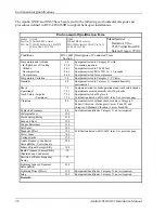
Specifications 

38 


Apollo GX50/60/65 Installation Manual 

I

NTERCOM 

P

ERFORMANCE 

(GX60/65

 ONLY

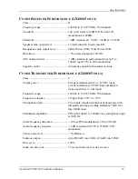
Microphone input......................................Two inputs, standard carbon or dynamic mic with 

integrated preamp providing minimum 70 mV rms 
into 1000

 load 

Headphone audio output level ..................280 mW into 100

, 120mW into 500


AGC characteristics ..................................output varies < 3dB with input of 100mV rms to 

1000 mV rms 

C

ONTROL 

I

NPUTS


Simulator select.........................................Must be connected to ground for normal operation, 

leave open for built-in simulator operation 

Hold select ................................................Waypoint sequencing hold input, connect to 

momentary button to ground for hold input 
operation, should be combined with the OBS/HLD 
annunciator  (optional on GX65) 

Transmit key (GX60/65) ...........................Input pulled low to ground to enable the transmitter 

Intercom select (GX60/65)........................Input pulled low to ground to enable the intercom 

function 

Flip/Flop (GX60/65) .................................Remote comm flip/flop input, connect to a 

momentary button to ground for remote flip/flop 
operation. 

A

NTENNA 

R

EQUIREMENTS


GPS


A

NTENNA


The GX50 and GX60/65 are designed to operate properly with the A-33 or A-34 GPS 
antennas. The GX50/60/65 supplies 5 volts for the antenna. 

C

OMM 

A

NTENNA


The Apollo GX60/65 requires a VHF comm antenna meeting the following specifications. 


Standard 50

 vertically polarized antenna with a VSWR < 2.5:1. 

S

ERIAL 

I

NTERFACE


RS-232 ......................................................Defined in Appendix E - Serial Interface 

Specifications 


Содержание APOLLO GX60

Страница 1: ...Apollo Model GX50 GPS Model GX60 GPS Comm Model GX65 GPS Comm Installation Manual September 2003 560 0959 04b ...

Страница 2: ...smitted disseminated downloaded or stored in any storage medium for any purpose without the express written permission of Garmin Garmin hereby grants permission to download a single copy of this manual and of any revision to this manual onto a hard drive or other electronic storage medium to be viewed for personal use provided that such electronic or printed copy of this manual or revision must co...

Страница 3: ...vironmental qualification information 04a 3 5 4 2 02 Added Transceiver Status data output 04b 9 18 03 Company name change IMPORTANT NOTE The conditions and tests required for TSO approval of this article are minimum performance standards It is the responsibility of those desiring to install this article on or within a specific type or class of aircraft to determine that the aircraft operating cond...

Страница 4: ...NOTES ...

Страница 5: ...NSIDERATIONS 9 MOUNTING CONSIDERATIONS 9 MINIMUM SYSTEM CONFIGURATION 9 ALTITUDE INPUT 9 HELICOPTER REQUIREMENTS 10 EQUIPMENT MOUNTING 10 MOUNTING TUBE INSTALLATION 11 UNIT INSERTION 12 UNIT REMOVAL 12 ELECTRICAL CONNECTIONS 14 POWER 14 AVIONICS OUTPUTS 14 SERIAL INTERFACE 14 SPEAKER AND HEADPHONE OUTPUTS GX60 65 ONLY 15 MICROPHONE INPUTS GX60 65 ONLY 15 TRANSMIT KEY INPUT GX60 65 ONLY 15 INTERCOM...

Страница 6: ...CONTACTING THE FACTORY FOR ASSISTANCE 44 APPENDIX B PERIODIC MAINTENANCE 45 LITHIUM BATTERY REPLACEMENT 45 EQUIPMENT CALIBRATION 45 REFERENCE OSCILLATOR GX60 65 45 CLEANING THE FRONT PANEL 45 APPENDIX C ENVIRONMENTAL QUALIFICATIONS 47 APPENDIX D ACCESSORIES 49 FROM GARMIN AT 49 COMMERCIALLY AVAILABLE 52 APPENDIX E SERIAL INTERFACE SPECIFICATIONS 55 MOVING MAP OUTPUT 56 BINARY NEAREST LIST DATA WHE...

Страница 7: ...STRATIONS FIGURE 1 GX50 FRONT PANEL 2 FIGURE 2 GX60 65 FRONT PANEL 2 FIGURE 3 FULL STACK MOUNTING TUBE SPACING 11 FIGURE 4 MOUNTING FRAME ASSEMBLY 13 FIGURE 5 CABLE ROUTING 13 FIGURE 6 REAR COAX CONNECTOR ASSEMBLY 17 FIGURE 7 TNC COAX CONNECTOR ASSEMBLY 17 FIGURE 8 GX50 60 65 POWER AND AVIONICS CONNECTIONS 18 FIGURE 9 APOLLO ACU TO APOLLO GX50 60 WIRING DIAGRAM 19 FIGURE 10 APOLLO ACU TO APOLLO GX...

Страница 8: ...Table of Contents iv Apollo GX50 60 65 Installation Manual NOTES ...

Страница 9: ...s installation and checkout procedures Includes complete specifications Includes limitations for the equipment and installation Includes troubleshooting information Includes periodic maintenance requirements Includes the environmental qualification form Includes information on accessories Includes serial data specifications APOLLO GX50 60 65 DESCRIPTION The Apollo GX50 GPS is a TSO C129a JTSO C129...

Страница 10: ...Introduction 2 Apollo GX50 60 65 Installation Manual Figure 1 GX50 Front Panel Figure 2 GX60 65 Front Panel ...

Страница 11: ...te safe altitude information Map Displays Full screen map with bearing distance to waypoint and zoom level Split screen map with distance speed bearing track crosstrack error To waypoint and zoom level Split screen with nav data and comm frequency display GX60 65 only Smart key 1 button map declutter Tri state On map waypoint selection for information direct to nomination Track up desired track up...

Страница 12: ...function Frequency memory and recall functions from navigation data base 10 last used 10 user stored Two microphone inputs 12 watt audio amplifier Remote flip flop input SYSTEM CONFIGURATIONS The GX50 60 65 can be installed in several configurations based upon individual requirements This includes VFR or IFR GPS navigation This section defines the minimum requirements VFR GPS NAVIGATION INSTALLATI...

Страница 13: ...ch altitude input from an altitude encoder converter or air data computer The GX50 60 65 can also be connected to other external devices such as an autopilot a moving map display connected to an RS 232 serial output an SL40 VHF Comm radio connected to an RS 232 serial output For GX50 units Fuel Airdata Computer e g Shadin Model ADC 200 COMM TRANSCEIVER GX60 65 For standalone installations the comm...

Страница 14: ...ts specified in CFR 47 Part 15 Radio Frequency Devices Subpart B Unintentional Radiators The Apollo GX50 60 65 software is designed and tested to RTCA DO 178B level C and ED 12B Level C Note Unauthorized changes or modifications to the GX50 60 65 may void the compliance to regulatory agency requirements and authorization for continued equipment usage UNPACKING THE EQUIPMENT Carefully unpack the eq...

Страница 15: ... washer 4 4 4 224 0404 4 40 x 1 4 SS flat head Phillips machine screw 6 8 8 245 0022 Crimp contact for dsub 20 to 24 awg wire 37 52 52 310 5184 xx Mounting frame 1 1 1 310 5188 xx Connector mounting plate 1 1 1 998 0048 3 32 hex driver 1 1 1 Manual kits Part number 564 0064 4xx 6xx 8xx 560 0961 xx GX GPS User s Manual 1 1 1 560 0959 xx GX50 GX60 Installation Manual 1 1 1 560 0928 xx GX GPS Approac...

Страница 16: ...15 SW TV Highway Fax 503 591 7766 Beaverton OR 97006 Crimp tool Astro Tool part 615708 Positioner Astro Tool part 616356 For pin p n 245 0027 ITT Cannon Phone 714 261 5300 1851 E Deere Ave Fax 714 575 8324 Santa Ana CA 92705 6500 Insertion tool ITT part 274 7006 000 Desc CIET 20HD Regular duty Crimp tool ITT part 995 0001 585 Desc M22520 1 01 Regular duty Locator tool ITT part 995 0001 244 Desc TH...

Страница 17: ...installing the mounting frame INSTALLATION CONSIDERATIONS MOUNTING CONSIDERATIONS The GX50 60 65 is designed to mount in the avionics stack in the aircraft instrument panel within easy view and reach of the pilot The standard package includes a mounting frame for ease of mounting connections and service of the unit Allow an additional one inch clearance to the rear of the mounting frame for connec...

Страница 18: ...plate should be attached to the mounting frame before installing the frame in the instrument panel The rear connector plate can be used to tie down the cable assemblies Use the supplied edge guard to protect the cable from sharp edges Connect the shield grounds directly to the connector mounting plate Once the cable assemblies the connector mounting plate and the mounting frame are assembled insta...

Страница 19: ... the instrument panel opening to allow ease of insertion and removal of the unit If the back of the unit bezel does not mount flush to the mounting tube the connector may not engage fully Secure the mounting tube to the instrument panel structure Mounting screw heads must not protrude into the mounting tube Be sure to use the appropriate screws so the unit will slide in and out freely The screws a...

Страница 20: ...vertighten The back of the bezel must only be flush to the mounting tube If the cam lock is hard to turn or the unit does not seat fully the unit is probably binding and the mounting tube should be checked UNIT REMOVAL To remove the unit from the mounting frame turn the screw counter clockwise with the hex driver to unscrew the cam lock mechanism The unit will begin to pull away from the mounting ...

Страница 21: ...Installation Apollo GX50 60 65 Installation Manual 13 Figure 4 Mounting Frame Assembly Figure 5 Cable Routing ...

Страница 22: ...e connected as appropriate for the particular installation The CDI HSI outputs may be connected to a dedicated CDI or HSI or to a shared indicator using an appropriate switching relay The avionics outputs available are listed in the Avionics Outputs specification on page 35 Connect the annunciator outputs to lamp indicators as described in the specifications The minimum connections required for di...

Страница 23: ...is inhibited when the intercom function is selected REMOTE FLIP FLOP INPUT GX60 65 ONLY The GX60 65 includes a remote flip flop input This is an optional input that can be connected to a remote mounted such as on the yoke momentary push button switch which pulls the input low to ground ANTENNA INSTALLATION AND CONNECTIONS COMM ANTENNA GX60 65 ONLY The GX60 65 requires a standard 50Ω vertically pol...

Страница 24: ...moving the antenna is not necessary Once the antenna mounting position has been prepared route the coax cable from the antenna to the GX50 60 65 Proper selection of coax cable and assembly of connectors is critical to GPS signal performance The cable loss from the antenna to the GX50 60 65 should be limited to a maximum of 4 dB Minimize the coax length for optimum performance and DO NOT coil exces...

Страница 25: ...Installation Apollo GX50 60 65 Installation Manual 17 Figure 6 Rear Coax Connector Assembly Figure 7 TNC Coax Connector Assembly ...

Страница 26: ...Installation 18 Apollo GX50 60 65 Installation Manual Figure 8 GX50 60 65 Power and Avionics Connections ...

Страница 27: ...Valid ACTIVE APPROACH OBS HOLD MSG GPS SEQ Obs Hold PTK CDI L CDI R From To Nav Valid VDI Nav Valid CDI L CDI R GS Up From To Nav Valid GS Valid 26 14 15 20 21 32 42 8 12 9 10 13 11 30 31 18 19 24 25 29 16 17 22 28 34 35 Power Vcc Ground 78 1 15 33 34 16 26 17 14 13 11 12 10 29 40 VDI Dn VDI Up 30 31 28 36 37 GS Dn GS Valid GS Valid 33 38 39 GS Valid Nav Valid GS Dn 23 41 Dimmer High Dimmer Low 43...

Страница 28: ...NAV Valid NAV Valid GS Up VDI Valid MSG PTK CDI L CDI R From To Nav Valid VDI Nav Valid CDI L CDI R GS Up From To Nav Valid GS Valid 26 14 15 20 21 32 42 10 11 30 31 18 19 24 25 29 16 17 22 28 34 35 Power Vcc Ground 78 1 16 17 14 13 11 12 10 29 40 VDI Dn VDI Up 30 31 28 36 37 GS Dn GS Valid GS Valid 33 38 39 GS Valid Nav Valid GS Dn 23 41 4 Dimmer High Dimmer Low 43 44 6 Lamp Test 5 NAV enable GPS...

Страница 29: ...Installation Apollo GX50 60 65 Installation Manual 21 Figure 11 Apollo 50 60 Connections with MD41 Annunciator Relay ...

Страница 30: ...Installation 22 Apollo GX50 60 65 Installation Manual Figure 12 RS 232 Serial Connections ...

Страница 31: ...Installation Apollo GX50 60 65 Installation Manual 23 Figure 13 GX60 65 Comm Wiring Diagram ...

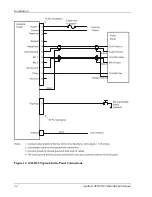
Страница 32: ...Installation 24 Apollo GX50 60 65 Installation Manual Figure 14 GX60 65 Typical Audio Panel Connections ...

Страница 33: ...tputs Check the avionics output connections by using the test mode as follows Rotate the LARGE knob to select each test 1 Using the CDI TRIANGLE page rotate the SMALL knob to check left mid and right 2 Using the VDI TRIANGLE page rotate the SMALL knob to check down mid and up 3 Using the TO FROM FLAG page rotate the SMALL knob to check the Off To and From outputs 4 Using the LAMP OUTPUTS page rota...

Страница 34: ...ls Mic Gain Set the microphone gain for microphones 1 and 2 for values from 0 to 255 1 In the Test Mode rotate the LARGE knob to select Mic Gain 2 Press SEL to activate selection The Mic 1 value will flash 3 Turn the SMALL knob to change the value 4 Turn the LARGE knob to the Mic 2 value Turn the SMALL knob to change the value 5 Press ENTER to accept and save the settings Receiver Squelch Preset t...

Страница 35: ...ing turned on the seed position may have to be re entered Entering the seed position 1 During the display startup sequence press SEL when the position page is displayed 2 Rotate the LARGE knob to move the cursor to different fields rotate the SMALL knob to input the correct lat lon and then press ENT to save the changes The seed position can also be input with reference to a waypoint Refer to the ...

Страница 36: ...mm antenna coax at the rear of the comm unit Note Older VHF comm transmitters may emit higher levels of harmonic interference causing greater problems and may be more difficult to deal with VHF COMM CHECKOUT GX60 65 Receiver Transmitter Operation Tune the unit to a local frequency and verify the receiver output produces a clear and understandable audio output Verify the transmitter functions prope...

Страница 37: ...nt then press ENT Or use the nearest search function to select a waypoint 4 Verify the bearing and distance to the selected waypoint If the database is expired or if a different coverage area is needed contact the Garmin AT factory for an update INTERFACE CHECKS The interfaces to other equipment such as the SL40 or a moving map display should be checked Make sure the other equipment is connected a...

Страница 38: ...uel Air Data Computer In the System Mode check the Misc Sensors function If the following steps do not show the correct information check the electrical connections and configuration setup 1 Press SYS Turn the LARGE knob to Misc Sensors and press ENTER 2 The Encoding Altimeter value will be displayed 3 Turn the LARGE knob to view Air Data Info 4 Turn the LARGE knob to view Fuel Info Autopilot The ...

Страница 39: ...____________ ____________ Port 1 _____________ ____________ Port 2 GPS NAVIGATION CHECKOUT Seed position entered Interface Checks Time date entered N A RS 232 outputs checked GPS Operation N A Map Mapcom Position check N A GPSS Signal reception check N A RS 232 inputs checked Interference from other avionics checked N A Altitude Encoder VHF comm interference check N A NAV N A F ADC VHF COMM CHECKO...

Страница 40: ...Installation 32 Apollo GX50 60 65 Installation Manual NOTES ...

Страница 41: ...dio transmit max at 90 modulation at 1000 Hz Input power GPS navigation input 7 watts typical Input power comm input 3 7 watts typical receive 28 watts typical transmit Internal fuses Nav input 3 amp fast blow surface mount on board Comm input 7 amp fast blow soldered in board Fuses must be replaced with the same or equivalent type contact the factory Memory backup Internal lithium battery with a ...

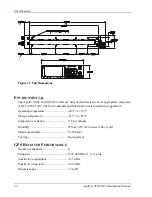
Страница 42: ... is included in Appendix C Operating temperature 20 C to 55 C Storage temperature 55 C to 85 C Temperature variation 2 C per minute Humidity 95 at 50 C for 6 hours 2 day cycle Maximum altitude 55 000 feet Cooling Not required GPS RECEIVER PERFORMANCE Number of channels 8 Frequency 1575 42 MHz L1 C A code Sensitivity acquisition 135 dBm Sensitivity drop lock 142 dBm Dynamic range 20 dB Figure 15 Un...

Страница 43: ...rive up to 200 ohm load Nav valid flag 300 mv for valid indication will drive up to 100 ohm load Nav superflag Vin 2 volts minimum for valid source capability of 400 mA VDI up down 150 mv full scale will drive up to 200 ohm load VDI valid flag 300 mv for valid indication will drive up to 100 ohm load VDI superflag Vin 2 volts minimum for valid source capability of 400 mA Annunciators Open collecto...

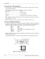
Страница 44: ...put are included on pages 67 to 68 ANNUNCIATOR REQUIREMENTS The GX50 60 installed for IFR non precision approach operation requires the following annunciators upper annunciator pictured below Each annunciator should include a lamp of the proper voltage for the installation The lower annunciator is suitable for the GX65 Legend Color MSG amber PTK blue or white OBS HLD blue or white with included mo...

Страница 45: ...erride COMM TRANSMITTER PERFORMANCE GX60 65 ONLY Class 4 Output power 8 watts minimum carrier at 12VDC input 6 watts minimum at 10VDC input transmit is locked out below 9 volts input Frequency range 118 000 to 136 975 MHz 760 channels Frequency tolerance 15ppm from 20 C to 70 C Microphone input Two inputs standard carbon or dynamic mic with integrated preamp providing minimum 70mV rms into 1000Ω l...

Страница 46: ... hold input operation should be combined with the OBS HLD annunciator optional on GX65 Transmit key GX60 65 Input pulled low to ground to enable the transmitter Intercom select GX60 65 Input pulled low to ground to enable the intercom function Flip Flop GX60 65 Remote comm flip flop input connect to a momentary button to ground for remote flip flop operation ANTENNA REQUIREMENTS GPS ANTENNA The GX...

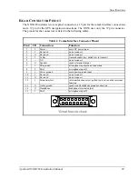
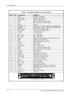
Страница 47: ...1 I Power main DC power input 2 I Reserved do not connect 3 O Reserved do not connect 4 I TxKey transmit enable key pulled low to transmit 5 NC do not connect 6 O Speaker speaker terminal output 7 I Mic ground microphone input ground connection 8 I Mic 1 microphone input 1 9 I Power ground main power ground input 10 I Reserved do not connect 11 O Reserved do not connect 12 I Intercom select interc...

Страница 48: ... Left output 15 O ACTIVE Approach Active annunciator output GX50 60 only 16 O MSG Message annunciator output 17 O PTK Parallel track annunciator output 18 reserved do not connect 19 reserved do not connect 20 O Serial ground RS 232 signal ground 21 I RxD2 RS 232 channel 2 serial data input 22 O TxD2 RS 232 channel 2 serial data output 23 reserved do not connect 24 O reserved do not connect 25 O Gr...

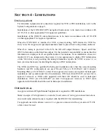
Страница 49: ...ystem it is not appropriate to display DST information on the SL30 that is not providing the tuning information Apollo SL30 SW version 1 2 or later provides the means for disabling the display of DST information The GX60 and GX65 are qualified for helicopter installation only when the correct mounting hardware and GX configurations are used Mount Tube p n 310 5184 01 and Connector Mounting Plate p...

Страница 50: ...Limitations 42 Apollo GX50 60 65 Installation Manual NOTES ...

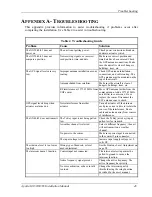
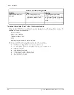
Страница 51: ...na Add a 1575 42 MHz notch filter in comm coax Fix or replace the comm Disconnect the ELT antenna coax to check GPS signal levels drop when avionics are turned on Noise interference from other avionics Turn all avionics off then turn on each piece one at a time to isolate the source of the interference Route cable and antenna away from sources of interference The GX60 65 does not transmit The TxKe...

Страница 52: ...oblem check the electrical system CONTACTING THE FACTORY FOR ASSISTANCE If the Apollo GX50 60 65 unit fails to operate despite troubleshooting efforts contact the Garmin AT factory for assistance Garmin AT Inc 2345 Turner Rd SE Salem Oregon 97302 USA Phone 503 581 8101 or 1 800 525 6726 Be prepared with the following information about the installation Installation configuration accessories antenna...

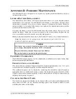
Страница 53: ...placed only with Garmin AT part 148 1702 or a Garmin AT approved equivalent Caution The battery may explode if mistreated Risk of fire explosion and burns Do not recharge disassemble heat above 100 C or incinerate Dispose of batteries promptly Keep away from children Be sure the battery is inserted in the right direction EQUIPMENT CALIBRATION The GX50 60 65 design requires very few adjustments or ...

Страница 54: ...Periodic Maintenance 46 Apollo GX50 60 65 Installation Manual NOTES ...

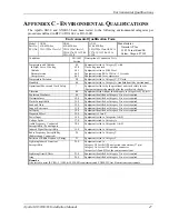
Страница 55: ...hout shock mounts to Categories B M N Explosion Proofness 9 0 Equipment identified as Category X no test required Waterproofness 10 0 Equipment identified as Category X no test required Fluids Susceptibility 11 0 Equipment identified as Category X no test required Sand and Dust 12 0 Equipment identified as Category X no test required Fungus Resistance 13 0 Equipment identified as Category X no tes...

Страница 56: ...y A standard humidity environment Shock Operational Crash Safety Impulse Sustained 7 2 7 2 1 7 3 1 7 3 2 Equipment tested for both operational and crash safety shocks Equipment operated normally after 20g shocks Equipment tested at 20g levels Certification based on DO 160C tests See previous page Vibration 8 0 Equipment tested without shock mounts to Category U Robust Vibration Helicopter Curves F...

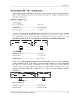
Страница 57: ... base It has a maximum altitude of 55 000 feet and weighs only 3 9 oz See the installation manual for the A 33 for complete specifications and installation instructions A 34 Antenna Garmin AT Part 590 1112 Manufacturer Aero Antenna Manufacturer AT 575 93 The A 34 GPS antenna is an optional accessory item with the GX50 60 65 The A 34 includes a built in preamp and has a low profile low drag radome ...

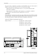
Страница 58: ...nsmitter in a residential or industrial environment is not permitted without an appropriate FCC license Annunciators These Apollo ACU annunciators provide the required annunciation for the GX50 60 for IFR en route terminal and non precision approach operation See the instructions provided with the annunciator module for complete specifications and installation instructions Apollo ACU GPS NAV Annun...

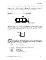
Страница 59: ...button The following annunciator provides the required annunciation for the GX65 for IFR en route and terminal operation See the instructions provided with the annunciator module for complete specifications and installation instructions The annunciator should be connected to a suitable dimming circuit for night operation Audio Panel The Apollo SL10 audio panel includes audio selection and a six pl...

Страница 60: ...y installation several annunciator control units are available that combine the required annunciators switches and navigation source selection relays The MD41 Series GPS annunciator control unit from Mid Continent Instruments includes all required annunciation for the GX50 60 for non precision approach and source selection relays The unit is available in both horizontal and vertical configurations...

Страница 61: ...Technology NAT Series 582 switch annunciator from Eaton Altitude Encoders Converters The GX50 60 65 can use altitude data from encoder or converter units that output information on an RS 232 serial interface Check the altitude input requirements on page 36 The serial interface specifications required from the encoder or converter units are included in Appendix E Several altitude encoders compatibl...

Страница 62: ...1212 Wichita KS 67207 Fax 316 683 1861 Avionics International Supply Inc Phone 214 248 2233 4389 Westgrove 800 553 2233 US Dallas TX 75248 Fax 214 250 2794 Northern Airborne Technology Phone 604 763 2232 1925 Kirshner Road Suite 14 Fax 604 762 3374 Kelowna B C Canada VIY 4N7 For altitude encoders and gray code converters Shadin Company Incorporated Phone 612 924 1141 6831 Oxford Street Fax 612 924...

Страница 63: ...with SL40 comm data NAV MAPCOM Nav info input of frequency identifier and OBS resolver value from Apollo SL30 Moving map data output with SL40 comm data ALTENC GPSS Altitude encoder converter data input GPS Steering info output to autopilot ALTENC NONE Altitude encoder converter data input no output ALTENC MOVMAP Altitude encoder converter data input moving map data output ALTENC MAPCOM Altitude e...

Страница 64: ... Figure 17 Baud rate 9600 Data bits 8 Stop bits 1 Parity none Output rate approx 1 seconds Message length variable approx 83 to 750 characters The serial output messages are in the following format STX id data it id data it id data it ETX STX ASCII start of text character 1 byte 02h id item designator 1 byte from following table data item data format listed in following table it item terminator 1 ...

Страница 65: ...ed ddd knots E ddddd 5 Distance to active waypoint ddddd nm x 10 G sdddd 5 Cross track error s sign R for right L for left of course dddd distance off course hundredths of nm I dddd 4 Desired track magnetic dddd degrees x 10 K ddd dd 3 to 5 Active waypoint identifier ddd dd ASCII waypoint identifier L dddd 4 Bearing to active waypoint magnetic dddd degrees x 10 Q sddd 4 Magnetic variation s sign E...

Страница 66: ...ifier 10 11 12 sddddddd xxmmmmmm xhhhhhhh Waypoint latitude packed unsigned binary s sign 0 for north 1 for south ddddddd degrees mmmmmm minutes hhhhhhh hundredths of minutes x undefined 13 14 15 16 sxxxxxxx dddddddd xxmmmmmm xhhhhhhh Waypoint longitude s sign 0 for east 1 for west dddddddd degrees mmmmmm minutes hhhhhhh hundredths of minutes x undefined 17 18 nnnnnnnn nnnnnnnn Magnetic variation ...

Страница 67: ...y a shorter record will be sent with the List Item Number set to 0xFF Table 8 Nearest Waypoint List Data Byte Format Description 1 Z Z Item Designator 2 sddddddd List Item Number Packed unsigned binary values s 1 End of list 0 all other ddddddd 1 20 list waypoint index sddddddd 0xFF List Type is EMPTY BYTE 4 terminate Item 3 t Waypoint Type t a airport v VOR n NDB i INT u USER 4 Cr r Item Terminat...

Страница 68: ...m Format Len Description a eampht 8 Annunciator Flags e Approach Enabled off O on a Approach Active off O on B blink m Message off O on B blink p Parallel Track off O on h Hold off O on B blink t From To off T To F From c vDddd 7 CDI v Nav Flag Flagged v Valid D Needle C Center L Left R Right ddd Deflection Value ASCII 000 120 l lower case L dddddd 6 Distance to Destination dddddd nm 10 p sdddd 7 ...

Страница 69: ... n NDB i intersection u user p parallel track d direct to F FAF E DME I IAF H MAHP M MAP A IFAF P undefined approach waypoint type Example Moving Map Data Output Extended Data Disabled AN 34 1570 34 15 70 latitude BW 118 4390 118 43 90 longitude C306 306 track angle D210 210 knots E02682 268 2nm to waypoint GR0006 0 6nm right of course I3059 305 9 desired track KSFO SFO waypoint ident L3058 305 8 ...

Страница 70: ...it checksum is converted to two ASCII characters by taking the upper and lower nibbles adding 30h to each and placing the most significant character first in the data message Example Moving Map Data Output Extended Data Enabled AN 34 1570 34 15 70 latitude BW 118 4390 118 43 90 longitude C306 306 track angle D210 210 knots E02682 268 2nm to waypoint GR0006 0 6nm right of course I3059 305 9 desired...

Страница 71: ...atory frequency 6 AWS automatic weather station 3Eh CTR Center 7 CLR clearance delivery 3Fh undefined for other frequency types mk frequency m desired frequency in MHz in hexadecimal where m desired frequency 30h with the desired frequency in the range of 118 to 136 MHz or 162 MHz k desired frequency in kHz where k desired frequency 25 kHz 30h with the desired frequency in the range of 000 to 975 ...

Страница 72: ...to 45h k kHz where k desired kHz offset 25 kHz 30h with desired frequency range of 000 to 975 kHz in 50 kHz steps or the even numbers from 30h to 56h Note that the field will be checked to ensure that it is in range and a valid VOR frequency Frequencies used for localizers which are in the range of 108 10 to 111 95 MHz will not be accepted in this message type Example message PMRRV20UBG Sp E chksm...

Страница 73: ...izer frequency data used for the remote recall function The data consists of three characters to identify the runway associated with the localizer followed by two characters defining the frequency Message format V Message Class This is a VHF NAV message 23 Message Identifier iiii Station or Runway identifier This field will provide an identifier for the localizer which can be either the actual sta...

Страница 74: ...e 41 Message identifier rrrr Range from DME station in 1 10th of a nautical mile units The first two digits are the 10s and 1s place of the range and the last digit is the 1 10th s place This field may range in value from 0 0 NM 0000 to 999 9 NM 9999 If the distance from the DME station is greater than 999 9NM the value should be encoded as sss Ground speed with respect to DME station in knots Thi...

Страница 75: ...ude in feet right justified with leading zeros 11 T ASCII T 054h 12 or Temperature sign ASCII or 02Bh or 02Dh 13 14 dd Internal altimeter temperature 15 16 dd Checksum of bytes 1 through 14 computed in hex output in ASCII format i e FA hex 17 CR ASCII carriage return 0Dh The altitude input can decode several status or error codes These codes would be in place of the altitude data in characters 5 1...

Страница 76: ...le 512 character max The serial input message string is expected in the following format STX message message message chksum ETX STX ASCII start of text character STX 02h message starts with an ASCII S then an ID character followed by the message data a carriage return CR 0Dh and a line feed LF 0Ah See the Altitude Sign Altitude in Feet Temperature Sign Example 1 Altitude Encoder Internal Temperatu...

Страница 77: ...in degrees Celsius SH ddd WDIR 7 Wind Direction 0 to 359 degrees from true north SI ddd WSPD 7 Wind Speed in knots SJ sdd TURN 7 Rate of Turn in degrees second is right is left SK sddd VSPD 8 Vertical speed in tens of feet minute SL ddd HEAD 7 Heading 0 to 359 degrees from true north SM dddd RFF 8 Right Engine Fuel Flow in tenths of gallons hour SN ddddd RFU 9 Right Engine Fuel Used in tenths of g...

Страница 78: ...ed LF 0Ah See the following table checksum the message checksum same format as message ETX ASCII end of text character ETX 03h Example Fuel Airdata Input Data STX SA223 223 knots indicated air speed SB230 230 knots true air speed SC101 0 101 mach SD 3200 32 000 feet pressure altitude SE 3312 33 120 feet density altitude SF 05 5 C outside air temp SG 03 3 C true air temp SH010 wind direction at 10 ...

Страница 79: ...d VSPD 8 Vertical speed in tens of feet minute ZL ddd HEAD 7 Heading 0 to 359 degrees from true north ZM dddd RFF 8 Right Engine Fuel Flow in tenths of gallons hour ZN ddddd RFU 9 Right Engine Fuel Used in tenths of gallons ZO dddd LFF 7 Left Engine Fuel Flow in tenths of gallons hour ZP ddddd LFU 9 Left Engine Fuel Used in tenths of gallons ZQ ddd ERR 7 Error Log Reason Indicator 001 temp sensor ...

Страница 80: ...t id data it id data it EXT where STX is the ASCII start of character 1 byte 0x02 id is the item designator 1 byte i e B data is the item data see item format in following pages it is the item terminator 1 byte Cr 0x0d ETX is the ASCII end of character 1 byte 0x03 Table 14 Ascii Autopilot data Id Item Format Len Item Description C ddd 3 Track magnetic ddd degrees D ddd 3 ground speed ddd knots E d...

Страница 81: ...or 0h to 27h in 25kHz steps 1 s digit is not shown on the display mk Standby frequency m MHz where m 30h desired MHz frequency of 118 to 136 162 or 76h to 88h A2h k kHz where k 30h desired kHz offset of 0 to 39 or 0h to 27h in 25kHz steps 1 s digit is not shown on the display a Transceiver status I intercom R normal receive M monitor selected T transmit enabled S stuck mic s Squelch test setting A...

Страница 82: ...Serial Interface Specifications 74 Apollo GX50 60 65 Installation Manual NOTES ...

Страница 83: ... altitude encoder may be installed A serial version is the perferred option In this diagram the parallel installation is identified by 8 The audio ground and mic ground connections may use a common point on the audio panel 9 Not all audio panel connections are shown on this drawing due to the variances in installations Consult the SL15 installation manual 10 If the installation is utilizing gray c...

Страница 84: ...Full Stack Drawing 76 Apollo GX50 60 65 Installation Manual ...

Страница 85: ......

Страница 86: ......

Отзывы: