


Service-Manual, new version
author: Chr. Fuchs 17.06.99 / INDUCS Ltd. 18.09.03
page 19 of 28
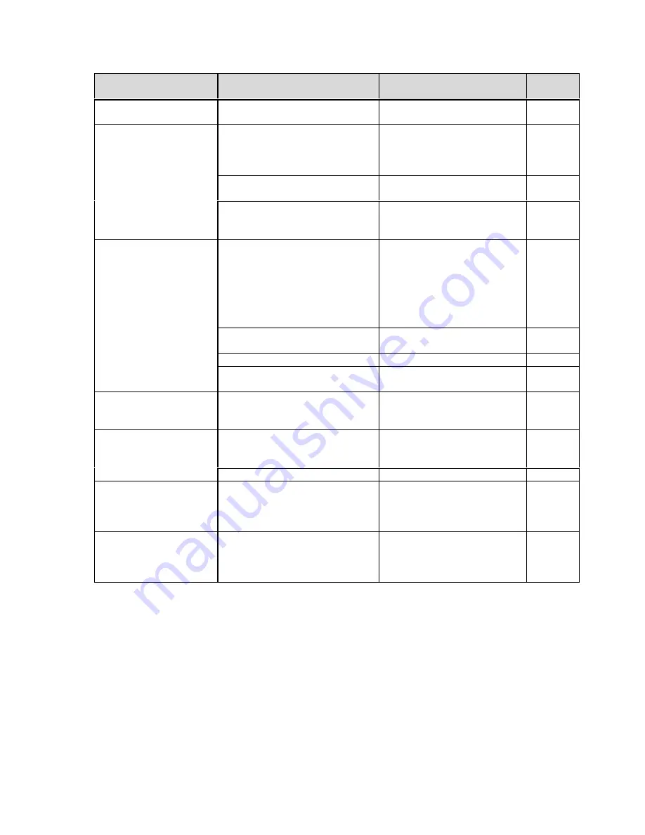
Fault
Possible cause
Action to take through
authorized personnel
Nr.
No heating with small
pans
Pan detection wrong adjusted
Contact your supplier
AL2
Poor heating
, indicator
lamp is ON (flashes)
Used pan is not ideal
Chose a pan that is
recommended for induction
cooking. Compare results
with your pan.
Potentiometer defective
Check potentiometer
AO2
Air cooling system is obstructed Make sure that the air
supply und air exit are not
obstructed
Poor heating
Ambient temperature is too high
(the air cooling system cannot
hold the cooker in the normal
operating temperature 2)
Make sure that no hot
ambient air is sucked in by
the fan. Reduce the
temperature of the ambient
air. The temperature of the
air supply may not exceed
40
º
C/ 110º F.
One phase is missing (only with
three phase supply)
Check the fuses
Power print defective
Check power print
AP3
Logic print defective
Verify logicprint
AL3
No reaction on
turning the control
knob
Potentiometer is defective
Check potentiometer
AO3
Heat rating switches
off
and on
within
minutes
, fan is working
Air cooling system is hindered
Make sure that air supply
and air exit are not hindered,
clean air slots
Fan is dirty
Clean fan
AF1
Heat rating switches
on and off within
minutes
, fan does not
work
Fan defective
Fan checking defective
Check fan
AF2
Heat rating switches
on and off within
minutes
(after a long
and constant use)
Coil is overheated, heating area
is too hot
Empty pan
Overheated oil in the pan
Switch off cooker, put pan
away and wait until the
heating area has cooled
down.
Содержание SH/BA 3500
Страница 15: ...Service Manual new version author Chr Fuchs 17 06 99 INDUCS Ltd 18 09 03 page 15 of 28...
Страница 16: ...Service Manual new version author Chr Fuchs 17 06 99 INDUCS Ltd 18 09 03 page 16 of 28...
Страница 17: ...Service Manual new version author Chr Fuchs 17 06 99 INDUCS Ltd 18 09 03 page 17 of 28...


