background image

 User Guide 

 EdgeSafe: Bypass TAP | P10GSFPA | 4.24.1 


 Installation Procedure 

 1. T 

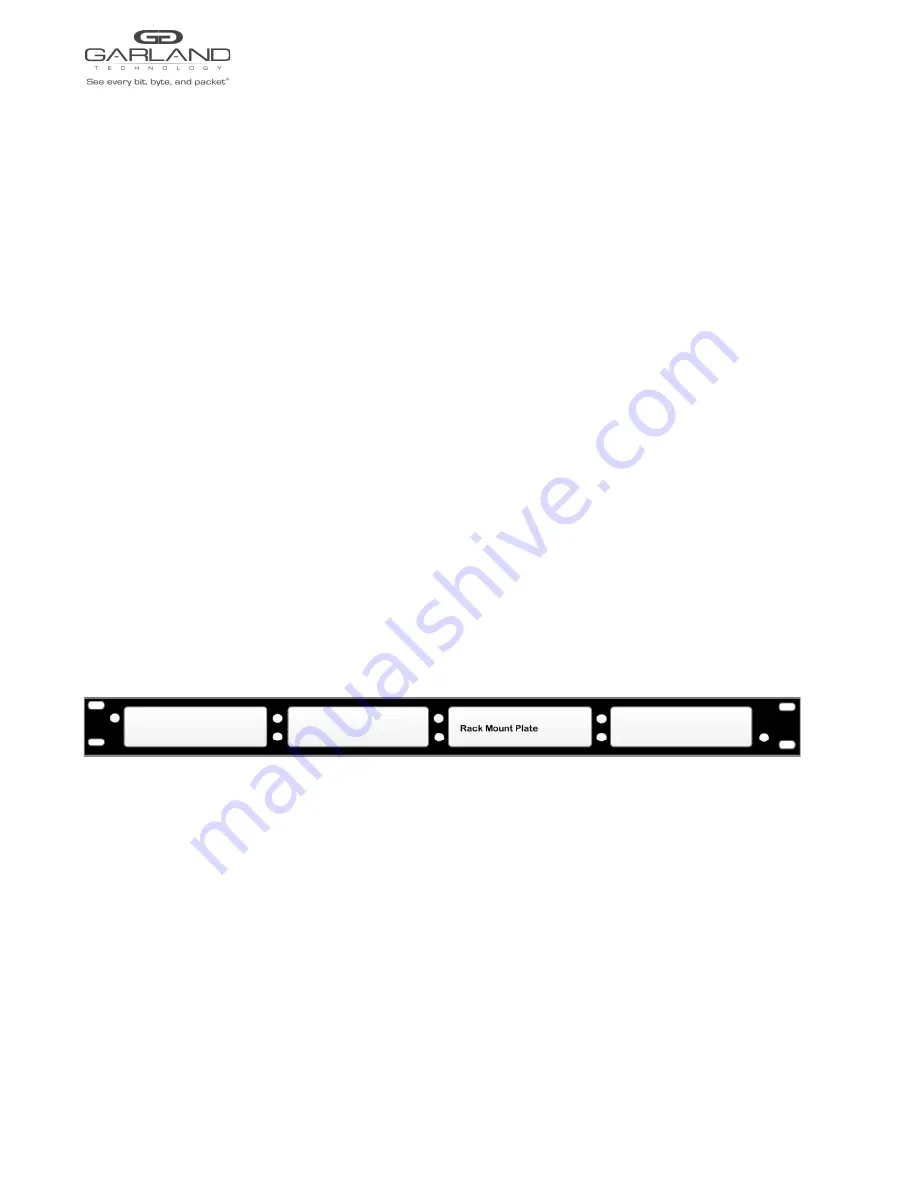
 he P10GSFPA may be installed in any available  1U slot of a network rack and secured with rack 

 mount screws or in the optional rack mount bracket, sold separately. The optional rack mount bracket 
 is shown below. 

 2. Set the switches on the rear of the unit for the desired speed, LFP option and application. 

 3. Connect power cables to P 

 S 

 1 and P 

 S 

 2 on the rear  panel and plug into available power sources. 

 4. Verify that the PS1 LED and PS2 L 

 ED 

 on the rear  panel are illuminated. 

 5. Insert the correct SFPs for the desired speed and application. This step can be done prior to power on 

 if desired. 

 6. Connect the cables or fibers to the desired ports per the application. 

 7. Verify the L/A LEDs are illuminated green indicating link. 

 8. Verify the L/A LEDs are flashing green indicating link and traffic. 


 Optional Rack Mount Bracket 

 Garland Technology  |  716.242.8500  |  www.garlandtechnology.com/support 

 8 

 Copyright © 2023 Garland Technology, LLC. All rights reserved. 

Содержание P10GSFPA

Страница 1: ...User Guide P10GSFPA 03 2023 Version 4 24 1 Garland Technology 716 242 8500 www garlandtechnology com support 1 Copyright 2023 Garland Technology LLC All rights reserved...

Страница 2: ...purchased products services and features are stipulated by the contract made between Garland Technology and the customer All or part of the products services and features described in this document ma...

Страница 3: ...Mode 5 Breakout Mode 5 Aggregate Mode 5 Aggregate 2 Mode 5 Span Mode 5 Span Packet Inject Mode 6 Rear Panel 6 LED Indications 6 Switch Settings 7 Installation Procedure 8 Optional Rack Mount Bracket...

Страница 4: ...ect LFP and Fail Mode open are supported on the network ports for the bypass breakout and aggregate modes Front Panel LED Indications Port 1 LFP LFP LED Port 1 L A Link Activity LED Port 2 LFP LFP LED...

Страница 5: ...Port Ingress Port 1 Port 2 Port 4 Aggregate Port Ingress Port 1 Port 2 Aggregate 2 Mode Port 1 Network Port Ingress Span Port 3 Port 4 Port 2 Network Port Ingress Span Port 3 Port 4 Port 3 Aggregate S...

Страница 6: ...Span Port Ingress Port 1 Packet Inject Port Egress Port 1 Port 3 Span Port Ingress Port 1 Packet Inject Port Egress Port 1 Port 4 Span Port Ingress Port 1 Packet Inject Port Egress Port 1 Rear Panel L...

Страница 7: ...Aggregate 3 Off 4 On 5 Off Span 3 On 4 On 5 Off Span PI 3 Off 4 Off 5 On Aggregate 2 3 On 4 Off 5 On Switch 6 7 8 N A N A 6 Off 7 Off 8 Off LFP is not supported for 1G and 10G copper applications Swi...

Страница 8: ...nd PS2 on the rear panel and plug into available power sources 4 Verify that the PS1 LED and PS2 LED on the rear panel are illuminated 5 Insert the correct SFPs for the desired speed and application T...

Страница 9: ......

Отзывы: