5300 Carbon Fiber Telescopic Volleyball System
6
Floor Sleeve Installation
1.
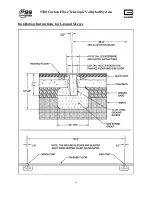
Mark (2) points on the floor exactly 36 feet apart (refer to most recent set of architectural
prints for exact locations within the gym). These represent the CENTERS of each sleeve
installation. If sleeves are to be more or less than 36 feet apart, contact a PSS or Gared
representative for information regarding this alteration.
2.
Cut (2) round holes through the playing surface 4-3/4” to 5” diameter centered on the
spots marked in step one. (See page 7)
3.
After cutting out the circle in the surface flooring, cut a similar hole in the concrete slab
below. The diameter of this hole should be about 5”; however the size is not critical.
The hole must be large enough to accommodate the sleeve at 3 degrees off vertical.
4.
Cut or drill the hole completely through the concrete slab. Under the slab, hollow out (by
hand) an area about 16-20” deep from the playing surface. (Refer to page 5 and 7)
5.
A “non-shrink” grout should be used to anchor the sleeve. Pour the grout mixture into the
hole until it is just below the BOTTOM of the concrete hole. Cover the sleeve during
installation to prevent debris from falling in or grout from entering the bottom of sleeve.
6.
Insert the 3-1/2” O.D. steel sleeve and work it down into the grout until
the inside bottom of the sleeve is 11” below the TOP surface of the
floor. Incorrect sleeve depth will result in a net height error. Also be
aware that the sleeve must tilt 3º away from the court. The 3º will
correct when the net is installed and tightened.
Note: 3
o
is
approximately 9/16” in 11”.
7.
Wait a minimum of (7) days to allow the grout to cure before setting up
the posts.
8.
Note: A skilled woodworker will be needed for the following operation!
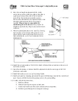
Using a router and template, make a
counterbore 6-7/16” diameter by 9/16” deep
centered over the original 5” hole in the floor,
to receive the brass floor cover. A template
can be made from a piece of Masonite or thick
plastic. A template is needed to achieve a good
and accurate cut. Many router and template combinations are possible. One
example of a router and template combination is shown on page 6. A finished
counterbore of 6-7/16” diameter is what is important! Practice on a piece of scrap
wood first. If the hole is too big, corrections may not be possible!
9.
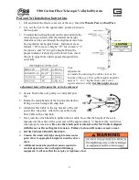
Install the floor covers. Usually the covers are oriented to open outward away from the
playing area. However, this is a matter of preference. Drill holes and insert screws as
shown on page 8.
Court
Содержание 5300 Series
Страница 4: ...5300 Carbon Fiber Telescopic Volleyball System 3...
Страница 8: ...5300 Carbon Fiber Telescopic Volleyball System 7 Installation Instructions for Ground Sleeves...
Страница 9: ...5300 Carbon Fiber Telescopic Volleyball System 8 Counterbore Details and Floor Cover Installation...
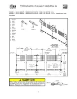
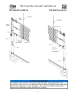
Страница 12: ...5300 Carbon Fiber Telescopic Volleyball System 11 5306 Winch Post with Net 5307 End Post with Net...

