level of the liquid being pumped. When taking suction from a
tank or vessel, position the inlet above the maximum expected
level of solids. Use full-bore ball valves or gate valves to mini-
mize restriction. Suction strainers should be properly sized to
minimize pressure drop and positioned for easy cleaning access.
If start-up screens are used, be sure they are removed prior to
placing the system into regular operation. Orient lines so as to
prevent formation of air pockets. Be sure all joints are tight. Flush
out all suction lines prior to installing the pump.
General Piping
For further ease of maintenance, use union fittings to connect the
pump to the system. Install a discharge priming tee for conven-
ience. Do not spring the piping to connect the pump. Use piping
supports or hangers as required. When necessary, provide for
thermal expansion and contraction to avoid placing strain on the
pump. Be sure that connecting pipe male tapered threads are not
undersize. Properly sized pipe threads will tighten adequately and
(with proper thread sealant) will seal properly without risk of con-
tacting the gears and interfering with pump performance. For
non-metallic pumps, plastic threads require finger tight connec-
tions & joint sealing compound such as Loctite® Pipe Sealant
with Teflon® or equivalent. Over tightening will cause cracks.
Alignment
Proper alignment is key to all variations of seals and packing as
well as bearing performance. Improper alignment can lead to pre-
mature pump failure. Check the alignment carefully between the
pump and the drive.
Belt Drive
Ensure that the pump and motor shafts are parallel and in line. Be
sure that the belt tension is adequate (per the belt manufacturer's
recommendation) but do not overtighten. For heavy pulley loads,
external ball bearing supports should be incorporated. A single ½"
(A or 4L section) V-belt is satisfactory for drive speeds up to 1 HP
3450 RPM. For larger drive sizes, double-V belts are recom-
mended. Install guards around all moving parts in accordance
with OSHA to prevent personal injury.
Pressure Relief
Discharge lines should be fitted with properly sized line pressure
relief valves to protect both the pump and the system. The relief
outlet should be piped back to the suction vessel. Relief valves
are available through your Oberdorfer representative.
Fasteners
Unless the pump has been shipped directly from the factory, it is
recommended to check all bolts and nuts for tightness to eliminate
possible leakage problems or destructive vibration. Chemsteel®
pump housing fasteners are factory installed to the following
torque specifications:
(top of page)
Flow By-Pass
When a flow by-pass system is used to control output from the
pump, the bypassed fluid should be directed back to the suction
vessel to avoid recirculation heat build-up. In cases where this is
not possible, connect to the suction at least 10 pipe diameters
length away from the pump inlet. Provisions for cooling should
be made in the event of recirculation heat build-up.
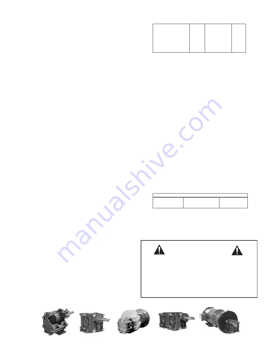
Pump Driver Mounting
Adapter kits (including faceplate, bracket, coupling components,
and hardware) are available for the full line of Chemsteel® Gear
pumps allowing Close Coupled connectivity to NEMA and IEC
motor frames. Assembly instructions are included with each kit.
Base mount kits (including baseplate, coupling components, cou-
pling guard, and hardware) are also available for all Chemsteel®
Gear pumps. Contact your Oberdorfer representative for addi-
tional information.
Seals
Packing:
For proper operation, the packing area must be cooled
and lubricated. Where packing lubricant is required, use it.
Recommended lubricants include:
Where pump is equipped with lantern ring and recirculating flush,
check for proper piping from pump discharge to lantern ring nip-
ple. Where thorough flush of lantern ring packing area is intend-
ed, check flush stream piping.
Pump
Bolt
Thread
Bolt / Nut Head
Torque
Metal - Series S1
M6
10 mm hex
45 in-lbs
Metal - Series S2
M6
10 mm hex
45 in-lbs
Metal - Series S4
M8
13 mm hex
85 in-lbs
Metal - Series S9
M8
13 mm hex
85 in-lbs
Non-Metallic - Series S2
M6
5 mm hex socket
25 in-lbs
Non-Metallic - Series S9
M8
6 mm hex socket
35 in-lbs
Service
Lubricant
Typical Source
Solvents
Soap-free grease
Keystone 5P9
Acids/Alkalies
Fluorocarbon grease
Halocarbon 25/20M
High Temperatures
Silicone/Carbon/Graphite
Dow Corning 41
Follow National Electrical Code.
Verify that electrical service is properly grounded,
fused, and adequately sized for motor
nameplate requirements. Check to be sure that
motor wiring connections are correct referring
to the wiring diagram on the motor nameplate
or inside the terminal box.
WARNING
2
R1


