HF-7-602 Page 51
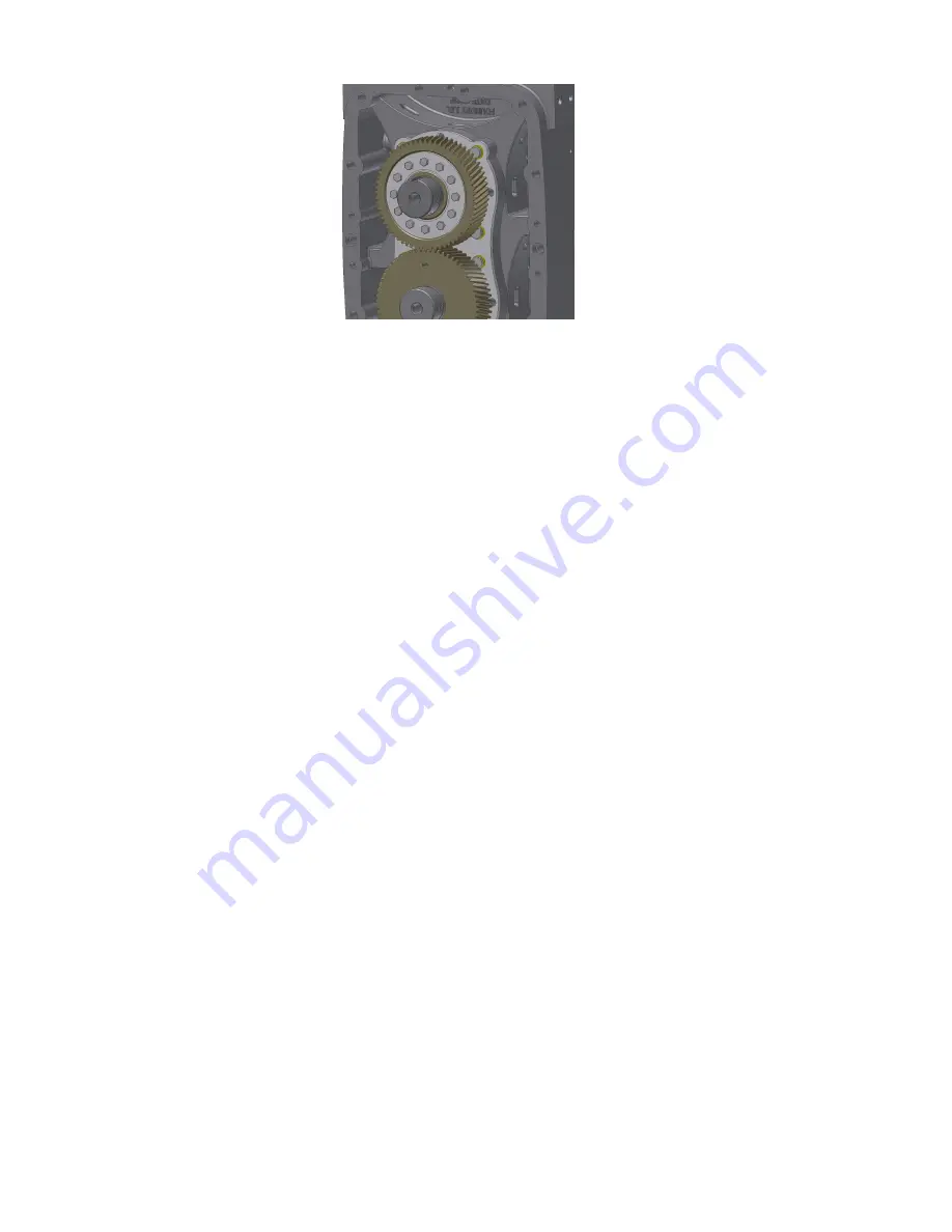
Figure 9-10 – SHRINK DISK/TIMING GEAR INSTALLATION
48. Verify total interlobe clearance. Through discharge port, insert feeler gauges between rotor lobes.
Measurement is taken at pitch diameter of rotor lobes, just above widest cross sectional width of
rotor lobe. Clearance is measured along entire length of meshing lobes for all three interlobe
meshes.
Total interlobe clearance: 0.017" min
49. Set closed side interlobe clearance. Closed clearance is measured between two meshing rotor
lobes inside air cylinder on leading side of drive rotor lobe as it rotates in same direction of arrows
cast in air cylinder. Measurement is taken at the pitch diameter of rotor lobes, just above widest
cross sectional width of the rotor lobe. Clearance is measured along the entire length of meshing
lobes for all three interlobe meshes.
49a. Lock idler rotor from turning by wedging a feeler gauge or shop rag between tip of a lobe
and air cylinder at inlet port. Through discharge port, insert a .007" feeler gauge
between leading side of drive rotor and meshing idler rotor (locked) and apply rotational
force to pull drive rotor tight against feeler gauge.
49b. While holding drive rotor tight against feeler gauge, apply rotational force to timing gear
in same direction until teeth firmly mesh against teeth on pinion gear. Using a socket,
tighten bolts of the gear locking assembly in a diametrically opposite sequence only
enough to secure timing gear to rotor shaft when applying rotational force by hand.
Ensure gear is pressed firmly against bearing inner race.
Closed side interlobe Clearance: 0.007" min
50. Verify open side interlobe clearance. Lock idler rotor from turning by wedging a feeler gauge or
shop rag Between tip of a lobe and air cylinder at discharge port. Apply rotational force to drive
rotor in same direction of cast arrows on air cylinder. Measure clearance by inserting feeler
gauge between trailing side of drive rotor and meshing idler rotor (locked) at pitch diameter of
rotor lobes through inlet port.
Open side interlobe Clearance: 0.010" min
51. Tighten shrink disk bolts to 30 in-lbs in a diametrically opposite sequence and verify interlobe
clearances are still within spec (See note below). Tighten shrink disk bolts to 106 in-lbs in a
diametrically opposite sequence. Repeat process to ensure screws will not turn when 106 in-lbs is
applied to them a second time.
Note:
Do not turn any screw more than 1/4 turn during torque process!
Содержание HELIFLOW HYEL AA
Страница 13: ...HF 7 602 Page 12 FIGURE 2 1 VERTICAL BLOWER MOUNTING CONFIGURATIONS AND OUTLINE 303HYE800 A Ref Drawing...
Страница 14: ...HF 7 602 Page 13 FIGURE 2 2 514 BLOWER MOUNTING CONFIGURATIONS AND OUTLINE 302HYE800 C Ref Drawing...
Страница 26: ...HF 7 602 Page 25 Figure 5 3 CARRIER SLINGER DRIVER EQ144211 3 Figure 5 4 INSERT DRIVER EQ144211 4...
Страница 27: ...HF 7 602 Page 26 Figure 5 5 FALSE BEARING EQ144211 5...
Страница 29: ...HF 7 602 Page 28 Figure 5 8 HAND CRANK EQ144211 8...
Страница 30: ...HF 7 602 Page 29 Figure 5 9 MECHANICAL SEAL DRIVER EQ144211 9...
Страница 31: ...HF 7 602 Page 30 Figure 5 10 FALSE BEARING SPACER EQ144211 10...
Страница 44: ...HF 7 602 Page 43 SECTION 8 PARTS LIST HYEL_AA 300HYE810 D Ref Drawing...
Страница 55: ...HF 7 602 Page 54 SECTION 10 PARTS LIST HYEL_AB 301HYE810 B Ref Drawing...
Страница 58: ......
Страница 59: ......


