17
www.gd-elmorietschle.com
© Gardner Denver Schopfheim GmbH
|
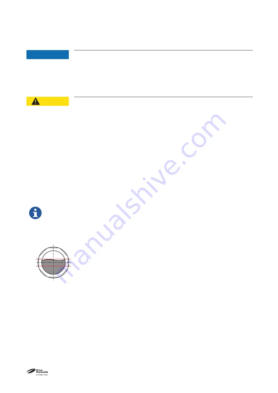
MAX
MIN
Fig. 6 Oil level
Installation
5.3 Connection of pipes
NOTICE
Material damage resulting from too high forces and torques of the pipes acting
on the unit!
If forces and torques during installation and operation are too high, the machine can
be damaged.
Ø
Only screw in pipes by hand.
Ø
If necessary, use flexible connections.
CAUTION
Risk of injury due to closed exhaust air opening!
Closed, restricted or covered exhaust air openings can cause too high back pressure
in the machine.
Ø
Never close or restrict the exhaust air openings.
Ø
Do not install any blocking devices.
Ø
Maximum permissible back pressure: + 50 mbar
If the back pressures are higher due to the process, please contact us.
Ø
Prevent liquids from accumulating in the exhaust line.
Ø
Regularly check the connected exhaust lines for pollution.
a) Remove the blind plug from the vacuum connection.
b) Connect the pipes with the vacuum connection (Fig. 2 3/A).
c) The exhausted air can be blown out through the exhaust air outlet (Fig. 2- 3/B) or conducted away using
a hose or pipeline.
To avoid distorting in the piping system, we recommend using compensators.
d) Check that the maximum back pressure is not exceeded!
The suction capacity of the vacuum pump is reduced if the inlet pipe is too narrow and/or too
long.
5.4 Check lubricating oil
a) Check the lubricating oil level through the oil sight glass (Fig. 23/I) and top up, if necessary.
b) Fill the lubricating oil for the gear wheels and bearings at the oil filling point (Fig. 2- 3/H) up to the middle
of the sight glass (Fig. 2- 3/I) .
Oil change and suitable types: see chapter 7.2.1 “Change the oil”, page 24


