


RTCC LED lighting controllers - User Manual
Where:
c
= output channel (1 to 4)
p
= trigger input (1 or 2)
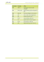
12.3.3 Trigger timing commands
Show status command
ZZ
This command shows the operational parameters of the digital
outputs. A typical output for the RTCC controller is:
Encoder: 1 line
OP1: MD=2, IP=1, GT=-, DL= 10.000ms, PL= 2.000ms, RT=
0.000ms, ioGefrp
OP2: MD=5, IP=2, GT=-, DL= 0.000K, PL= 0.001K, RT= 0.000K,
iogefrp
Where:
OP
Output channel number
MD
Mode for the output
IP
Input used for triggering
GT
Gate input for enabling/disabling the output
DL
Pulse delay
PL
Pulse width
RT
Retrigger delay
iogefrp
Flags used by output
Set the output mode
This command sets the configuration for an output channel. See
for a description of these parameters.
ZSc,m,i,g,f
Where:
c
Output channel number (1 to 4)
m
Mode
i
The trigger input:
0 for free running timer
1 to 4 for IP1 to IP4
5 to 8 for OP1 to OP4
—
53
—