background image

RTCC LED lighting controllers - User Manual

4

Sécurité

Lisez ce document avant d'utiliser le RTCC. Respectez les mesures de
sécurité suivantes en toutes circonstances. En cas de doute, contactez
votre distributeur ou Gardasoft Vision. Les symboles ci-dessous auront la
signification suivante:

Attention:

Lisez les instructions pour comprendre quels

sont les risques éventuels.

Attention:

La surface peut devenir chaude.

Attention:

 Risque d'électrocution.

Lorsque ces symboles apparaissent dans le manuel, reportez-vous aux
consignes pour connaître les précautions à prendre.

4.1

Chaleur

Veillez à ce que le RTCC soit monté correctement (voir

Section 5,

Mounting the RTCC

et à ne dépasser aucune valeur nominale pour l'unité

(voir

Section 13, Reference information

).

Lorsqu'il atteint ses valeurs nominales maximales, le boitier RTCC peut
dépasser les 65°C, ce qui est suffisant pour provoquer des brûlures en cas
de contact. Placez l'appareil à un endroit où le personnel ne risque pas de
le toucher par accident et veillez à ce que l'air circule librement autour de
l'unité.

4.2

Électricité

Le RTCC produit des impulsions d'énergie élevées. Veillez à bien
raccorder les sorties et à ce que les câbles de sortie et la charge soient à
l'abri de tout court-circuit. Lorsque le RTCC est éteint, de l'énergie
résiduelle reste dans l'appareil pendant environ 15 secondes.

Le RTCC ne possède pas d'isolation électrique complèt des entrées
(notamment des ports de déclenchement et de communication) et des
sorties. Par conséquent, respectez les consignes suivantes :

L'équipement informatique connecté aux ports de communication et de
déclenchement doit être alimenté en interne ou séparé de l'alimentation
secteur par une isolation double/renforcée, ou être approuvé selon la
norme CEI 60950-1. Tous les autres équipements branchés aux
déclencheurs ou à d'autres ports doivent aussi posséder une isolation
double/renforcée pour être protégés de l'alimentation secteur.

13

Содержание RTCC Series

Страница 1: ...RTCC LED Lighting Controllers Issue 002 User manual www gardasoft com ...

Страница 2: ...ipment cannot cause any dangerous situation or significant financial loss to occur Deliberate acts of endangerment and vandalism are not covered by this document and must be considered by the installer While care has been taken in the preparation of this document Gardasoft Vision Ltd will not accept any liability for consequential loss of any kind except those required by law All trademarks acknow...

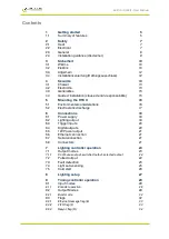
Страница 3: ...s 16 5 2 Electrostatic discharge 17 6 Connections 18 6 1 Power supply 18 6 2 Lighting output 18 6 3 Trigger inputs 20 6 4 Digital outputs 20 6 5 12V Power output 21 6 6 Ethernet connection 21 6 7 Serial connection 21 6 8 Connectors 21 7 Lighting controller operation 23 7 1 Output modes 23 7 1 1 Continuous output switched output selected output 24 7 2 Pulsed output 24 7 3 Fault detection 25 7 4 Lig...

Страница 4: ...0 2 2 Fixed IP address 42 10 3 Automatic sensing 42 11 Webpage configuration RTCC420 44 11 1 Main page 44 11 2 Configuration page 45 11 3 General setup page 46 11 4 Digital output configuration page 46 12 Command configuration 47 12 1 Ethernet configuration RTCC420 47 12 2 RS232 configuration RTCC460 47 12 3 Command structure 47 12 3 1 General commands 48 12 3 2 Lighting channel commands 51 12 3 3...

Страница 5: ... power supply as described in Section 6 Connections Read Section 8 Lighting setup the current or voltage rating of the lights and then connect the lights Set up the RTCC for the desired operation as described in the configuration sections Section 11 Webpage configuration RTCC420 and Section 12 Command configuration Visit www gardasoft com for application notes on this product There is also a Suppo...

Страница 6: ... controllers User Manual The table below lists the features on each model Number of channels Ethernet setup RS232 setup Fast pulsing RTCC420 4 Yes No No RTCC460 4 No Yes No RTCC420F 4 Yes No Yes RTCC460F 4 No Yes Yes 6 ...

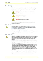
Страница 7: ... free flow of air around the unit 2 2 Electrical The RTCC produces high energy pulses Take care to connect the outputs correctly and protect the output wiring and load from any short circuits When switched off energy remains stored in the RTCC for about 15 seconds The RTCC does not have complete electrical isolation of inputs including triggering and communications ports and outputs therefore plea...

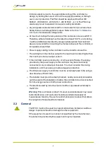
Страница 8: ...an the maximum channel output current If the controller is set up incorrectly or in the event of failure the energy provided by the power supply to the controller may become directly connected to any or all output channels You must consider this during installation and if necessary provide adequate protection The DC power supply to controller must be externally fused to 5A using a slow blow fuse T...

Страница 9: ... own risk assessment specific to each installation While Gardasoft Vision Ltd has taken every care in the preparation of this advice Gardasoft Vision Ltd accept no liability for damages of any kind except those required by law Deliberate acts of endangerment and vandalism are not covered by this document and must be considered by the installer 9 ...

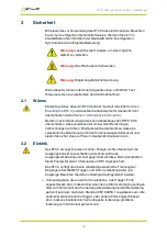
Страница 10: ...rennungen zu führen Positionieren Sie das Gerät so dass eine versehentliche Berührung durch das Personal ausgeschlossen ist und stellen Sie sicher dass Luft frei um das Gerät zirkulieren kann 3 2 Elektrik Das RTCC erzeugt Impulse mit hoher Energie Achten Sie darauf die Ausgänge korrekt anzuschließen und schützen Sie die Ausgangsverkabelung und Last gegen Kurzschlüsse Beim Ausschalten bleibt Energi...

Страница 11: ...gen Kontakt mit dem Metallgehäuse der Steuerung oder deren Kühlkörper sofern angebracht geschützt sein Die Verkabelung der Stromversorgung zur Steuerung muss für mindestens 5A bemessen sein Die Verkabelung vom Kanalausgang zur Last muss höher als der maximale Kanalausgangsstrom dimensioniert sein Wenn die Steuerung falsch eingerichtet ist oder im Fall eines Fehlers kann es vorkommen dass die von d...

Страница 12: ...eeinträchtigt werden 3 4 Installationsanleitung Haftungsausschluss Diese Informationen dienen nur zur Orientierung Installationstechniker müssen ihre eigene spezifische Risikobewertung für die jeweilige Installation durchführen Auch wenn Gardasoft Vision Ltd diese Empfehlung mit größter Sorgfalt erstellt hat übernimmt Gardasoft Vision Ltd keine Haftung für Schäden jeglicher Art außer in dem gesetz...

Страница 13: ...voquer des brûlures en cas de contact Placez l appareil à un endroit où le personnel ne risque pas de le toucher par accident et veillez à ce que l air circule librement autour de l unité 4 2 Électricité Le RTCC produit des impulsions d énergie élevées Veillez à bien raccorder les sorties et à ce que les câbles de sortie et la charge soient à l abri de tout court circuit Lorsque le RTCC est éteint...

Страница 14: ...ier en métal du contrôleur ou son dissipateur thermique s il est installé Le câblage d alimentation vers le contrôleur doit avoir une capacité minimale de 5A Le câblage reliant la sortie de la chaîne à la charge doit avoir une capacité supérieure au courant de sortie maximal de la chaîne Si le contrôleur est mal réglé ou en cas de panne l énergie fournie par l alimentation au contrôleur peut deven...

Страница 15: ...ltérée 4 4 Guide d installation clause de non responsabilité Ces informations sont seulement à titre indicatif Les installateurs doivent effectuer leur propre évaluation des risques pour chaque installation Même si Gardasoft Vision Ltd a préparé minutieusement ces conseils Gardasoft Vision Ltd décline toute responsabilité pour tout dommage quel qu il soit à l exception de ceux requis par la loi La...

Страница 16: ...e PP704 kit is available for mounting the RTCC on a DIN rail 5 1 Environmental considerations The enclosure is a fire enclosure as long as it is mounted so that none of the connectors are facing downwards If a fire enclosure is used the enclosure should be metal or plastic with a flammability rating of UL94 V1 or better with no holes below or to the sides of the when mounted Cable entries below th...

Страница 17: ...ischarge ESD can damage equipment and impair the electrical circuitry inside your RTCC ESD damage occurs when electronic components are improperly handled and can result in complete or intermittent failures On the RTCC this is relevant only to the trigger connections and power input 17 ...

Страница 18: ... ambient temperature The external power supply must be capable of supplying at least the average output power for all active channels We recommend you use a regulated power supply with 100 short circuit protection If however a non regulated power supply is used then the maximum ripple voltage of the power supply must not exceed 10 of the DC voltage Route the low voltage and mains wiring separately...

Страница 19: ...nt or voltage rating of your light before you connect it see Section 8 Lighting setup The connectors fitted to an RTCC series controller are shown in the illustrations below You should refer to Section 6 3 Trigger inputs for the pin allocations of the trigger connectors and Section 6 4 Digital outputs for the pin allocations of the digital outputs 19 ...

Страница 20: ... available as a trigger input if either encoder mode 1 or mode 2 is in use TRIG 4 is unavailable if encoder mode 2 is in use 6 4 Digital outputs The digital outputs are open drain as shown in the diagram opposite The voltage across the output must be no greater than 24V and it can sink no more than 50mA Note The output may be damaged if it is shorted to a voltage higher than 5V The table below des...

Страница 21: ...a network switch hub or router It operates at 10Mbits per second 10Base T 6 7 Serial connection The RS232 connector fitted to RTCC460 controllers is a standard 9 way female D type A standard straight through cable can be used to connect the controller to a PC serial port The communications port settings are 115Kbaud no parity 8 data bits and 1 stop bit The pin allocation for the serial connector i...

Страница 22: ...l Newark part number Power input 2W screw terminal free socket 691 351 500 002 164 1952 Trigger input 4W screw terminal free socket 691 361 100 004 184 1351 12V output 2W screw terminal free plug 691 348 500 002 N A Digital outputs 5W screw terminal free socket 691 361 100 005 184 1352 22 ...

Страница 23: ...trigger input is used as a trigger The delay from trigger to pulse the pulse duration and the brightness can be set Switched In switched mode a trigger input is used to switch the output current on and off The output is only enabled when the trigger input has a voltage on it Selected In selected mode a trigger input is used to select between two different intensities Tandem It is possible to conne...

Страница 24: ...nput The output current can be varied from 0 to 100 of full brightness 7 2 Pulsed output The output is off by default When the RTCC is triggered it waits for a delay and then pulses the output The delay pulse width retrigger delay and pulse intensity are all configurable Retrigger delay is the minimum allowed time from one trigger to the next Any triggers that happen too soon after the previous tr...

Страница 25: ...nal power dissipation is too high Output turned off 35 43 Output current to lighting is too low The light is open cir cuit or there is not enough supply voltage for the reques ted output current 36 If the output voltage is too low the controller detects that the output is short circuited 37 The voltage required for the lighting has increased too much Check for ageing of the lighting or a failed LE...

Страница 26: ...or the voltage rating Err 23 Current output is not what was expected The controller might need calibrating Err 23 The power rating of the light exceeds the maximum power rating 7 5 Cold start You can clear the RTCC configuration to its default settings this clears the lighting ratings and sets all channels to 50 brightness continuous operation You can do this by sending the CL command using Ethern...

Страница 27: ... voltage and wattage rating is given use the voltage rating Otherwise use the current rating For homemade lights using single LEDs or arrays of LEDs use the current rating from the LED datasheet You can set the current rating from 0 01A to 3A in steps of 0 01A and you can set the voltage rating from 12V to 36V in steps of 1V When you connect a voltage rated light the RTCC automatically senses the ...

Страница 28: ...t for IP3 and IP4 which can be used for an encoder as well as for general inputs 9 1 1 Encoder operation The RTCC supports two types of encoder one wire and two wire see the table below This can be configured using the ZE command or through the RTCC s web pages Mode Connections Operation Maximum frequency En1 one wire encoder IP3 is QEA Simple encoder provides position information All movement is ...

Страница 29: ...isables the output This is also used to specify the number of pulses in burst mode This parameter can be 0 for none 1 to 4 for IP1 to IP4 5 to 20 for OP1 to OP16 number of pulses for burst mode Pulse Delay Specifies the delay from trigger to pulse output This can either be a time period or a number of encoder pulses depending on the mode Pulse Width Specifies the width of the pulse output This can...

Страница 30: ...lses 4 Pulse ET PEt Pulsed output triggered by a digital input The delay is a number of encoder pulses The pulse width is a fixed time 5 Pulse EE PEE Pulsed output triggered by a digital input The delay and pulse width are a number of encoder pulses 6 Divide Trig Pd Pulse divider Every Pulse Delay trigger pulses the output is pulsed for Pulse Width time 7 Divide Enc Enc Pulsed output triggered by ...

Страница 31: ...se width and pulse spacing is a given number of encoder pulses 13 Counter Cou Sets the output as a counter The count does not start until the leading edge of the gate input After that the counter counts Pulse Delay leading edges on the trigger input The output is then pulsed for a period of Pulse Width 14 Min Pulse Trig iPF The trigger pulse must be a minimum width to cause an output pulse The out...

Страница 32: ... pulses 1 to 250 Pulse Width specifies the pulse width Pulse Delay specifies the separation between the start of one pulse and the start of the next 9 3 Flags Each output also has the following flags which specify other options For Ethernet commands multiple flags can be set by adding the flag values together Flag value Flag name Operation when flag 0 Operation when flag 1 1 I Trigger off leading ...

Страница 33: ...enting number from 0 to 255 Using the GT Ethernet command and the Ethernet message flag the RTCC sends the tag number in a message to the host computer to say that a trigger has occurred The message has the form Evt output tag Where output is the channel number from 1 to 16 and tag is a number from 0 to 255 Multiple tag messages may be sent in one packet separated by a semi colon 9 3 2 FIFO flag F...

Страница 34: ...not received in time then the product is rejected and an error code output 9 3 4 Pulse flag P The Pulse flag is used to select whether a pulse is needed to reject or to accept a product when the Resync flag is set When not set a pulse is required to reject product If a pass fail message is not received in Resync mode the RTCC defaults to rejecting the product 9 4 Virtual outputs In addition to its...

Страница 35: ... light after 60ms and then a camera exposure 0 5ms later OP1 is used to trigger the camera and lighting channel CH1 is connected to the light OP1 can be used to trigger a fixed exposure time or to generate the exposure time Output Mode Input Gate input Pulse delay Pulse width Retrigger time Flags CH1 Pulse 1 60ms 5ms 0 OP1 2 1 0 4ms 4ms 0 9 2 Sequenced pulses A sensor detects the presence of a pro...

Страница 36: ...riggered at 25Hz continuously except when IP1 is high to indicate that the machine has stopped The camera is triggered on OP1 The configuration details for this are shown below Output Mode Input Gate input Pulse delay Pulse width Retrigger time Flags 1 2 0 1 0ms 100μs 0 G 4 Set free running trigger to 25Hz OP1 triggers continuously at 25Hz only when IP1 is low Note Flags are set to 4 to invert the...

Страница 37: ...s are set into pulse mode The pulse delay is a number of encoder pulses and the pulse width is a fixed time The flags specify the trailing edge of the trigger signal and that the output pulse is active low 9 5 Multiple exposures with different lighting A sensor on IP1 detects the presence of a product Four images need to be taken from one camera using four different lights at 40ms intervals CH1 CH...

Страница 38: ... delay OP1 triggers a camera There may be several products between the sensor and the camera The RTCC stores each of the triggers and then outputs a pulse after the correct delay The configuration for this is shown below Output Mode Input Gate input Pulse delay Pulse width Retrigger time Flags 1 2 1 0 10s 100μs 0 F 16 38 ...

Страница 39: ...ation details for this are shown below Output Mode Input Gate input Pulse delay Pulse width Retrigger time Flags 1 2 1 0 200ms 100μs 0 2 2 1 0 10s 1s 0 E R P 104 10 seconds after a trigger OP2 is set to pulse for 1 second to reject a product The camera trigger has the Send trigger message flag set So that when the product is detected a message is send to the image processing software The image pro...

Страница 40: ...y SN2 12 0 OP2 tag 12 fail so the reject pulse on OP2 was not cancelled 9 8 Resync and FIFO mode This example uses the same situation as the previous example but the products are 4 seconds apart so that when a product is detected there are already two others travelling towards the reject gate Image processing software processes the image which can take a variable length of time and then sends a pa...

Страница 41: ... usually connected to a network switch hub or router but you can connect it directly into the network port on a PC using a crossover cable 10 2 IP Address The RTCC needs an IP address to communicate over Ethernet There are two ways to get an IP address either programmed into the unit or using DHCP For DHCP mode the RTCC acquires its IP address subnet mask and gateway address from a DHCP server Oth...

Страница 42: ...n alternative fixed IP address on the Alternative Configuration tab You can find out what IP address is being used by a PC at any time by following the steps below i Go to the Control Panel ii Select Network Connections iii Right click on Local Area Connection Select Status iv Select the Support tab The IP address is displayed 10 2 2 Fixed IP address When using a fixed IP address you must ensure t...

Страница 43: ... source port 30311 destination port 30310 It is formatted as Gardasoft RTCC420 20 000000 111111111111 22222222 8 bit ASCII 44 characters where 000000 The serial number of the unit 111111111111 The MAC address in 6 HEX bytes 22222222 The IP address in 4 HEX bytes For example for RTCC420 20 serial number 12345 IP address 192 168 1 103 MAC address 00 0B 75 01 80 99 the packet is formatted Gardasoft R...

Страница 44: ... controller s IP address displayed in GardasoftMaint into your web browser which will display the Main screen GardasoftMaint software is available from www gardasoft com Downloads 11 1 Main page The main page shown below is the first to open when you access the RTCC s webpages This gives the controller s hardware and firmware revision levels and the serial number It also tells you the power being ...

Страница 45: ...et up all the parameters for each output channel Pressing the Submit button updates the RTCC configuration and saves the changes to non volatile memory On this page you can Change the current rating for the light View some measured voltages and the actual output current Set the output mode continuous pulsed or switched Set the pulse parameters 45 ...

Страница 46: ...ny Ethernet command from Section 12 Command configuration 11 4 Digital output configuration page The digital output configuration page allows you to set up the timing parameters and flags for the digital outputs For a description of these parameters and effect of setting flags refer to Section 9 Timing controller operation There is one configuration page for each digital output on the RTCC 46 ...

Страница 47: ...mmands sent by the host controlling PC All output generated by the command is returned in reply UDP or TCP IP packets The last character sent is greater than symbol Once this is received the host knows that the command has been completed We recommend that the host waits for the symbol before sending the next command UDP communications are not guaranteed to arrive so the host software must be able ...

Страница 48: ...are not saved permanently until you send the AW command Report the version of firmware running in the RTCC This command returns the firmware version For example VR returns RTCC420 20 HW02 V031 Set Internal Trigger Enable or disable the internal trigger When enabled all outputs are triggered simultaneously using an internal trigger signal This setting can be saved to non volatile memory using the A...

Страница 49: ... channels in the controller A typical output for RTCC420 controller is CH1 MD0 S50 0 0 0 DL1 000ms PU1 000ms RT0 0us IP1 FL0 CS0 000A RA0 000A CH2 MD0 S50 0 0 0 DL1 000ms PU1 000ms RT0 0us IP2 FL0 CS0 000A RA0 000 CH3 MD0 S50 0 0 0 DL1 000ms PU1 000ms RT0 0us IP3 FL0 CS0 000A RA0 000A CH4 MD0 S50 0 0 0 DL1 000ms PU1 000ms RT0 0us IP4 FL0 CS0 000A RA0 000A Where CH Channel number MD Mode 0 continuo...

Страница 50: ...ernet messages or m 1 to enable Ethernet messages When Ethernet messages are enabled any error reports are sent to the most recent UDP or TCP address from which a command has been received Messages are of the form Evtc e Where c the channel number 1 to 4 or 0 for no channel e event value see Section 13 5 Event codes Clear any Errors GR If Ethernet messages are not enabled the last event or error n...

Страница 51: ...the web pages still work The setting of this command is restored after a power cycle 12 3 2 Lighting channel commands Set the rating of a light This command sets the current or voltage rating for a light If a current rating is being set then the voltage rating value should be 0 VLo v c Where o output channel 1 to 4 depending on model v voltage rating 0 or 12 to 36 c current rating 0 or 10mA to 3A ...

Страница 52: ...ess setting requires a current greater than 20A or if the combination of pulse width and setting is not allowed RTc p d s RTc p d s r Where c output channel 1 to 4 p pulse width in milliseconds 0 02 to 999 d delay from trigger to pulse in milliseconds 0 02 to 999 s setting in percent s 0 to 999 r retrigger delay This parameter is optional Set the Option Flags REc m Where c output channel 1 to 4 m ...

Страница 53: ...IP 2 GT DL 0 000K PL 0 001K RT 0 000K iogefrp Where OP Output channel number MD Mode for the output IP Input used for triggering GT Gate input for enabling disabling the output DL Pulse delay PL Pulse width RT Retrigger delay iogefrp Flags used by output Set the output mode This command sets the configuration for an output channel See Section 9 2 Output Modes for a description of these parameters ...

Страница 54: ... command ZTc p d Where c Output channel number 1 to 4 p Pulse width time or encoder pulses d Pulse delay time or encoder pulses For example the following command sets output 2 to provide a 3ms pulse after 5000 encoder pulses ZT2 3ms 5K Note You should set the mode with the ZS command before setting the pulse timing Set the retrigger time The retrigger time is the minimum time from when an output i...

Страница 55: ...s returned if 200 encoder counts have been received since the RTCC was turned on The count is a 32 bit unsigned number and wraps to 0 when it reaches 232 Set the encoder mode This command sets the encoder type ZEe Where e 0 for turn the encoder off 1 for a one wire encoder 2 for a two wire encoder Set an output This command sets an output to a given logic level ZVc v Where c Output channel 1 to 4 ...

Страница 56: ...0 and VL1 if the input is logic 1 Override the state of an input This command can be used to override the state of an input The override is cancelled as soon as an edge is detected on the input MIc v Where c Input channel 1 to 4 v 0 to set the input to off 1 to set the input to on Show the state of an ouput ZOc Where c The output channel 1 to 4 This command returns VL0 if the output is logic 0 and...

Страница 57: ...ch mode RU RU1 75 25 Set channel 1 to selected mode at 75 and 25 RT RT2 3 4 50 Set channel 2 to 3ms pulses delayed by 4ms at 50 brightness RP RP1 2 Output channel 1 is triggered using output 2 RE RE1 3 Set channel 1 to ignore lighting errors and not prompt for the current rating of a light when it is connected TT TT1 1ms Set internal triggers every 1ms TR TR2 Trigger channel 2 ST ST2 Show configur...

Страница 58: ... 4 0 0 Set channel 2 to Pulse TE with gate on IP4 ZB ZB1 200 Set internal trigger period to 200ms ZE ZE1 Set encoder mode to single input EN EN Read the encoder count ZV ZV2 1 Set channel to to high level ZI ZI2 Read the state of input channel 2 MI MI4 0 Simulate input 4 being off ZO ZO1 Read the state of output channel 1 58 ...

Страница 59: ...tput power Lighting rating 12V to 36V in steps of 1V 100mA to 3A in steps of 5mA 12V to 36V in steps of 1V 100mA to 2A in steps of 1mA Operating modes Continuous strobe switch and selected Trigger input Opto isolated standard or inverted operation 3V to 24V Digital outputs Four 24V 50mA open drain outputs Pulse width RTCC4xx 20 microseconds to 1 second Repeatable to 0 1 microseconds Pulse width RT...

Страница 60: ...es the following limits apply Pulse current Pulse length limit 20A 100μs 12A 400μs 10A 1ms 5A 3ms Pulses of 2A or more for pulse widths longer than 2ms may cause an error or have a lower current towards the end of the pulse For fast pulse controllers RTCC4xxF the minimum pulse delay is about 2μs When overdriving or using the retrigger delay the minimum delay is around 5μs For pulse widths less tha...

Страница 61: ...ollers User Manual Pulse widths below 4ms are repeatable to within 1us and are not subject to variation even with other simultaneous events Pulse widths above 4ms are repeatable to within 100μs and are subject to variation 61 ...

Страница 62: ...and not recognised Err 3 Numeric value is the wrong format Err 4 Wrong number of parameters Err 5 This is a warning not an error One of the para meters is out of range The value of the parameter has been adjusted For example sending an RT or ZT command with a delay of 0 gets a reply of Err 5 The command is accepted but the delay is set to the minimum allowed value Err 19 A light has been connected...

Страница 63: ... has prevented SafePower voltage going too high Err 81 Too many FIFO events have been used and the RTCC has run out of storage 13 4 Fatal error codes Error number Reason Err 44 The RTCC is too hot The RTCC has a thermal cutout which operates around 65 C to 70 C depending on conditions Err 40 Err 41 Err 45 One channel is outputting more current than expected Err 47 Internal protection has prevented...

Страница 64: ...eject or accept statements back to the RTCC 128 A light has been connected and is working 129 A light has been connected but doesn t have a current or voltage rating 130 An over temperature error occurred 131 An over current error occurred 132 An error has occurred while autosensing the rating of a light 138 SafePower trainup has completed 139 SafePower trainup has failed or been cancelled 140 In ...

Страница 65: ...RTCC LED lighting controllers User Manual This page is left blank for your notes 65 ...

Страница 66: ...e 2017 Copyright 2017 Gardasoft Vision Ltd Gardasoft Vision Ltd Trinity Court Buckingway Business Park Cambridge CB24 4UQ UK tel 44 1954 234970 fax 44 1954 231567 Gardasoft LLC Oak Ridge Road Weare New Hampshire 03281 USA tel 1 603 657 9026 www gardasoft com ...

Отзывы: