background image

ZN-D212XE installation Guide 

01A.01 


10 


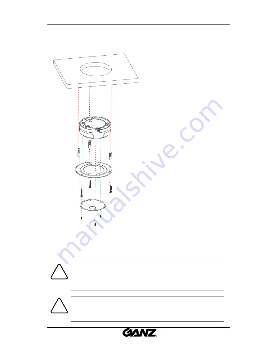
1)


Trace  the  size  on  a  surface  where 

the  device  will  be  inserted  with  the 
provided  template  and  create  a  hole.  
Also,  mark  on  a  surface  where  anchor 
blocks will be inserted. 

2) 

Drill  and  insert  anchor  blocks  on  a 

marked surface.


3)

 Connect all the appropriate cables to 

the  main  device  and  place  on  the 
center  of  the  hole.  Cables  should  be 
wired  from  other  side  of  the  exposed 
surface. 

 
4) 

Unscrew  3  bolts  that  are  on  the  dome 

cover’s  surface  and  place  the  FMB  mount 
in  between  the  top  dome  shelf  and 
bottom  circular  cylinder.  Align  to  the 
screws  holes  and  re-tight  3  components 
with bolts. 


5) 

Attach  the  dome  cover  on  main  body 

from  the  surface  side  where  it  will  be 
exposed  and  lock  it  up  by  rotating  the 
cover.


6) 

Tighten  the  mounted  surface’s  anchor 

blocks with screws on a FMB mount parts..


Caution

!


When placing the dome cover, look for carved triangle mark on both dome cov
er and main body. Both triangles should be aligned together when placing the c
over. Once the cover has been placed, rotate the dome cover for a secure lock. 
To detach the cover, rotate the dome cover and align two triangle marks, and 
pull the cover. 


Caution

!


To prevent products from damaging, place the camera on stable and non-vibrat
ing surfaces. If the stability is in doubt, consult with safety personnel for reinfor
cements, and then proceed with the installation. 

Содержание ZN-D212XE

Страница 1: ...IPN2102HD 5511 Installation Guide...

Страница 2: ...ONNEL FOR INTERNAL PARTS This symbol is intended to alert the user the presence of un insulated dangerous voltage within the product s enclosure which may be sufficient magnitude to constitute a elect...

Страница 3: ...ironment 15 6 1 1 Generic IP Environment 15 6 1 2 Custom IP Environment 16 6 2 View video on web page 17 6 2 1 View video using IPAdmin Tool 18 6 3 Reset 19 6 4 Factory Default 19 APPENDIX A SPECIFICA...

Страница 4: ...ming mode De interlacing on DSP Burnt in text supported Unicast Multicast supported Video Audio Video compression H 264 MJPEG 25 30FPS 1080p PAL NTSC Audio compression G 711 Law aLaw PCM Analog video...

Страница 5: ...carefully and handle the equipment with care The packaging contains Camera DC power adapter Quick installation guide 9 pin and 2 pin terminal blocks FMB mount for flush mount Screws and anchors Note...

Страница 6: ...ideo output mode No video output PAL NTSC Video Audio and IO terminal connector Connector for cable connection of audio input output and digital input output LAN connector RJ45 LAN connector for 10 10...

Страница 7: ...de 01A 01 7 4 INSTALLATION 4 1 Option A Semi Flush Mount Caution Installation template image s size scale in this installation guide is not 1 1 The correct size template design paper can be found insi...

Страница 8: ...Attach the dome cover on main body and lock it up by rotating Caution When placing the dome cover look for carved triangle mark on both dome cov er and main body Both triangles should be aligned toget...

Страница 9: ...01 9 4 2 Option B Flush Mount Caution Installation template image s size scale in this installation guide is not 1 1 The correct size template design paper can be found inside the package separ ately...

Страница 10: ...and re tight 3 components with bolts 5 Attach the dome cover on main body from the surface side where it will be exposed and lock it up by rotating the cover 6 Tighten the mounted surface s anchor blo...

Страница 11: ...01 11 4 3 Setting the Image Attribute Through the camera s webpage users can configure image settings The camera image s brightness contrast saturation and sharpness are adjustable through the image s...

Страница 12: ...It can be connected to either a voltage type sensor or a relay type sensor as the following figures Settings can be done through the camera s webpage Input voltage range 0VDC minimum to 5VDC maximum...

Страница 13: ...50mA Caution Do not exceed the maximum relay rating Caution Must connect GND port which is located between systems Video input output The camera provides 1 video out Video GND Red Black DO COM Relay T...

Страница 14: ...is a RJ45 LAN connector for 10 100 Base T Ethernet Connect a LAN cable When the device is connected the orange LED stays on while green LED continues to blink 12V DC Power A 12 DC power connector is r...

Страница 15: ...address 192 168 XXX XXX are used users may view the live streaming images on a web page using the device s default IP address 1 Convert the device s MAC address to the IP address Refer to the Hexadeci...

Страница 16: ...r customized network area 1 Find the device from the IPAdminTool s list and highlight the device s name 2 Right click the mouse and select IP Address IP Setup window appears 3 In the IP Setup s window...

Страница 17: ...view the live streaming images through a web browser The default username and password is root pass 1 The browser asks to install the ActiveX Click Allow 2 Setup exe installation link or pop up window...

Страница 18: ...ML 6 0 6 2 1 View video using IPAdmin Tool IPAdminTool automatically searches all activated network encoders and IP cameras and shows the product name IP address MAC address and etc IPAdminTool is pro...

Страница 19: ...t If you reset your device to the factory default setting all parameters including the IP address will be initialized For the Factory Default reset 1 Push reset button and hold for 5 seconds 2 Release...

Страница 20: ...PEG Selectable per Stream Number of Streams Dual Stream Configurable Resolution 1920x1080 1280x720 800x450 480x270 320x180 Compression FPS 30fps 1080p Motion Detection Built in Burnt in Text Digital V...

Страница 21: ...1 49 Vp p 39 K Audio Output Lineout 46mW Power 16 D I Max 50mA 5VDC TTL level 1 5V threshold D O Max 50mA 24VDC On state resistance 50 max continuous Environment Condition Operating Temperature Operat...

Страница 22: ...shorter than 140m and conform the PoE standard PoE compatibility With non Power Sourcing Equipment PSE When it is connected with non PSE the power adaptor should be connected With power adaptor Conne...

Страница 23: ...ZN D212XE installation Guide 01A 01 23 APPENDIX C DIMENSIONS Unit mm...

Страница 24: ...ZN D212XE installation Guide 01A 01 24 Unit mm...

Страница 25: ...235 0E 14 33 51 58 88 7D 125 A2 162 C7 199 EC 236 0F 15 34 52 59 89 7E 126 A3 163 C8 200 ED 237 10 16 35 53 5A 90 7F 127 A4 164 C9 201 EE 238 11 17 36 54 5B 91 80 128 A5 165 CA 202 EF 239 12 18 37 55...

Страница 26: ...ZN D212XE installation Guide 01A 01 26 REVISION HISTORY MAN DATE M D Y Comments 01A 01 05 21 2012 First release version...

Отзывы: