background image

11

MAINTENANCE & ADJUSTMENTS

Tension Calibration Procedure

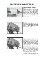
Step 1
Set the tension to 60 lbs. as indicated by the
linear scale and rotary knob. Place the string
on one end of a tension calibrator into a
string clamp and secure. Place string lo-
cated on the other end of the calibrator into
the string tensioner and apply tension. If the
brake lever releases before 60 lbs. or after
60 lbs., the tension head should be cali-
brated as follows.

Step 2
Loosen the 1.5 mm locking set screw (A)
located on the side of the latching block as
shown. The set screw is used to hold the
adjustment screw in place.

Step 3
If the lever releases before 60 lbs., using the
supplied L-shaped hex wrench, turn the
adjustment screw (B)  located on the left
side of the latch block counter-clockwise to
increase the engagement of the brake re-
lease latch with the brake lever. Repeat step
1 and adjust until the correct tension is
indicated on the calibrator.

If the tension indicated in step 1 is greater
than 60 lbs., turn the adjustment screw
clockwise to reduce the engagement of the
brake release latch with the brake lever.
Repeat step 1 and adjust until the correct
tension is indicated on the calibrator.

Tighten locking set screw (A) when finished.

B

A

Содержание Progression STII

Страница 1: ...OWNER S MANUAL Issue 5 January 2009 STII STRINGING MACHINE ...

Страница 2: ...ed on page 13 Tension Calibration as described on page 11 Tensioner Brake Adjustment as described on page 12 and Clamp Base Locking Nut Adjustment as described on page 13 GAMMA s obligation under this warranty is limited to repair or replacement of defective EQUIPMENT and no one is authorized to promise any other liability GAMMA shall in no event be liable for any incidental or consequential damag...

Страница 3: ...stem Accomodates All Racquets Without Adapters Parallel Jaw String Gripper w Diamond Dust Coated Gripping Surfaces Professional Quick Action Diamond Dust Coated Fixed String Clamps Durable Polystyrene Base Cover w Convenient Padded Tool Tray Strong Light Weight Aluminum Construction ...

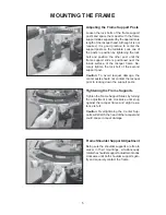
Страница 4: ...lt from the mounting plate that sets inside the central cavity of the turntable There are large holes stamped on the underside of the turntable that allow you to support the mounting plate with your fin gers while removing the mounting bolt After removing the mounting bolt remove and discard the plastic washers that are installed for shipping purposes Support Post Installation cont d Place the sup...

Страница 5: ...ge 7 for more details about this feature Turntable Brake The turntable may be locked in any position Flip the lever up to lock the turntable brake and flip the down to release the turntable brake Clamp Head Installation The post of the string clamp head and tube of the string clamp base are treated with grease to provide protection against corro sion during shipping Remove any exces sive grease wi...

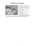
Страница 6: ...ely tighten the lock bolt of the second support post Caution To avoid racquet damage the center posts should not contact the racquet prior to locking down the support posts Tightening the Frame Supports Tighten the Frame Support Slides by turning the adjustment knob clockwise until snug against the racquet frame and slight resis tance is felt Caution Overtightening the Center Sup ports will stretc...

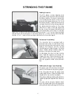
Страница 7: ...ost Re tighten all of the frame supports in the same order as before Do not overtighten any of the supports as racquet damage may occur The supports should be tightened to the point where the racquet frame will not move in the mounting system when the handle is grasped and attempts are made to move it Should any supports lose contact with the frame while stringing they should be re tightened ...

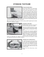
Страница 8: ...pport Tensioner Travel Stop The tensioner bar is equipped with a tensioner travel stop to limit travel of the tensioner along the bar and prevent contact between the tensioner and the racquet mounting system while stringing The travel stop is located about midpoint along the tensioner bar below the gear track To disengage the stop pull and hold the knob rotate 90 degrees and release To engage the ...

Страница 9: ...to the clamped position and back generally requires the rotation permitted by the slot in the clamp base If the rotation is not sufficient to allow smooth operation of adjust the Clamp Base Locking Nut as outlined on page 13 Clamp Head Operation Quick Action Clamps are of a dual action design where the clamp head and clamp base operate independently of one another To clamp a string lift the clamp ...

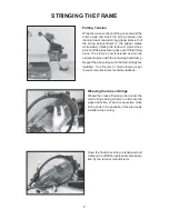
Страница 10: ...be clamped in place with the remaining fixed clamp Repeat the above steps until all main strings are installed Tie off ends of main strings as per racquet manufacturers recommendations STRINGING THE FRAME Weaving the Cross Strings Weave the cross strings over and under the main strings being careful to alternate the weave direction of each consecutive cross string so as to be opposite of the previ...

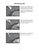
Страница 11: ...the same manner as for traditional awls The Pathfinder awl must be in the closed position before insertion Once the awl is inserted pull the handle of the awl outward while holding the tip section in place leaving the outer sheath in the grommet hole Insert the end of the string into the center of the sheath While holding pressure on the string slowly pull the sheath out of the grommet hole to lea...

Страница 12: ...tching block as shown The set screw is used to hold the adjustment screw in place Step 3 If the lever releases before 60 lbs using the supplied L shaped hex wrench turn the adjustment screw B located on the left side of the latch block counter clockwise to increase the engagement of the brake re lease latch with the brake lever Repeat step 1 and adjust until the correct tension is indicated on the...

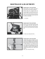
Страница 13: ...h insert the 6 mm hex wrench through the hole in the tensioner cover and into the B brake lever adjusting bolt B Brake Lever Adjustment Bolt Adjusting the Tensioner Brake To tighten the braking mechanism turn the brake lever adjusting bolt counter clockwise about 1 8 turn Retighten the lock bolt on the back side of the tensioner frame and check for brake tightness The tensioner should move freely ...

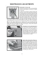
Страница 14: ...amp leaves impressions or damages the string it may be exces sively tight and should be adjusted by turning the hex screw counter clockwise to open the gap between the jaws The clamp jaws should be cleaned periodically to be free from dirt oil and any string coating for them to grip properly Note The string clamps supplied with your stringing machine can accomodate tight string patterns such as ba...

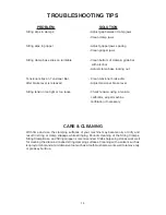
Страница 15: ...ol such as a toothbrush also works well to remove oily or greasey build up 14 TROUBLESHOOTING TIPS PROBLEM SOLUTION String slips in clamps Adjust gap between clamp jaws Clean clamp jaws String slips in gripper Adjust gripper jaws spacing Clean gripper jaws String clamp base slips on turntable Clean bottom of clamp glide bar with alcohol Adjust clamp base locking nut Tensioner slips on Tensioner Ba...

Страница 16: ...15 NOTES ...
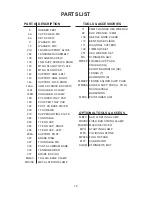
Страница 17: ...LATE TURNTABLE TT END CAP TT END CAP RIGHT TT END CAP LEFT SUPPORT POST BRAKE RING TURNTABLE PIN PII ST ALUMINUM BASE TENSIONER BAR BRAKE BOX ST TALL QA BASE CLAMP METAL STRING CLAMP 71 98 109 110 171 196 251 MA MFSPP MMSPP MMSSA MPSA MBFC MDCSC MGSMC MPG MPS MPXFS MTC SGSM 6MM T HANDLE HEX WRENCH BOX WRENCH 10MM NEEDLE NOSE PLIERS BENT NOSE PLIERS DIAGONAL CUTTERS 17MM SOCKET HEX WRENCH SET STRIN...

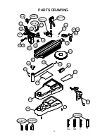
Страница 18: ...17 MFSPP SQ SB T B 5 104 MQAC MDCSC 335 192 189 MMSPP 320 190 337 270 21A 9 282 105 6A 143 144 140 141 146A 283 285 286 336 327 MMSPP MMSSA 8A MFSPP 296A 133 14 148L 142 PARTS DRAWING ...

Страница 19: ...GAMMA SPORTS 200 Waterfront Drive Pittsburgh Pennsylvania 15222 Phone 800 333 0337 Fax 412 323 0317 Visit our website at www gammasports com Copyright 2009 GAMMA Sports All Rights Reserved ...

Отзывы: