background image

5

ASSEMBLY INSTRUCTIONS

Fixed Clamp Installation

To install the clamps, remove the winged
lock knob to separate the knob from the
lower guide bushing. Be careful not to lose
the thrust bearing components located in the
center recess of the knob.

Align the clamp base with the clamp slot of
the turntable base. Insert the lower guide
bushing into the clamp from the bottom of
the turntable making sure to engage the
guide with the clamp slot.

Installing the Frame Support Posts

The GAMMA 5002 support post assemblies
are  precision aligned at the factory and are
marked for proper installation on the turn-
table.

Install the support post with the dot on its
base to an identical dot on the turntable.
Align the threaded hole in the bottom of the
frame support post with the slot in the turn-
table. Screw the lever lock bolt with washer
into the bottom of the support post and
tighten gently.Position the washer with the
rounded edge toward the turntable. Repeat

procedure on the opposite side of the turntable.

Installing the Turntable

The turntable is located on top of the foam
packing in the the shipping carton.

Insert the center post of the turntable into the
bushing located in the top of the tensioner
bar post.

Содержание 5002

Страница 1: ...OWNER S MANUAL Issue 1 Version 1 June 23 1998 5002 STRINGING MACHINE Copyright 1998 GAMMA Sports All Rights Reserved...

Страница 2: ...e GAMMA s obligation under this warranty is limited to repair or replacement of defective EQUIPMENT and no one is authorized to promise any other liability GAMMA shall in no event be liable for any in...

Страница 3: ...Diamond Coated String Gripper Tension Range 11lbs 89lbs 6 Point Mounting System DiamondCoatedDualActionSwivelCompositeStringClamps Full 360 Degree Turntable Rotation Large Convenient 141 sq in Tool Tr...

Страница 4: ...ons Align the holes in the leg flange with the matching holes in the lower column support post Secure the leg with one FLAT HEAD cap screw through the upper hole and one SOCKET HEAD cap screw through...

Страница 5: ...er the top of the upper column support and let it rest loosely on the bellows assembly Tension Track Installation Place the tube of the tension track assembly over the top of the upper column support...

Страница 6: ...semblies are precision aligned at the factory and are marked for proper installation on the turn table Install the support post with the dot on its base to an identical dot on the turntable Align the...

Страница 7: ...ted The post of the string clamp head and tube of the string clamp base are treated with grease to provide protection against corro sion during shipping Remove any exces sive grease with a clean cloth...

Страница 8: ...taneously rotatetheshouldersupportadjustmentknobs clockwiseuntilbothshouldersupportsgently and squarely contact the frame Tighten the Frame Support Slides at the head and throat of the racquet until t...

Страница 9: ...he string clamp and the clamp base operate independently of one another To clamp a string lift the clamp head and place the string between the jaws Depress the clamp head lever to secure the string Th...

Страница 10: ...lamping procedure to unlock the string clamp The winged lock knob should be tightened enough to prevent clamp base slippage on the turntable when the desired tension is placed on the string To go from...

Страница 11: ...er the main strings being careful to alternate the weave direction of each consecutive cross string so as to be opposite of the previously installed cross string Once the final cross string is tension...

Страница 12: ...nner as for traditional awls The Pathfinder awl must be closed before inser tion Once the awl is inserted pull the handle of the awl outward while holding the tip section in place leaving the outer sh...

Страница 13: ...your machine may become oily or dirty and result in string or clamp slippage while stringing Periodic cleaning of the following parts is recommended String Clamps Clean the inside gripping surfaces of...

Страница 14: ...the latching block as shown The plastic screw is used to hold the adjust ment screw in place Tension Calibration Procedure Step 3 If the lever releases before 60 lbs using the supplied L shaped hex w...

Страница 15: ...bolt should only be loosened until loose enough to turned by hand and must not be removed completely C Brake Adjustment Bolt C Adjusting the Tensioner Brake Step 3 With the hex bolt loosened and the...

Страница 16: ...15 COMPONENTS 54A 57A 57 58 52 55 56 114 116A 120A 106 119 117 111 104 112 115 113 121 9 6B 118...

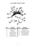
Страница 17: ...FRAME SUPPORT SLIDE BADMINTON ADAPTER TENNIS ADAPTER SUPPORT SLIDE KNOB MTNG STAND TOP PLATE PART 141 142 143 144 145 146 147 148 DESCRIPTION MTNG STAND PAD SUPPORT ARM LEFT SUPPORT ARM RIGHT SHOULDE...

Страница 18: ...ide Bushing Nut 57 Load Bushing 57A Radial Thrust Bearing 58 Winged Knob 104 Tensioner Assembly 106 Wing Locking Knob Screw 111 Tensioner Track 112 Tool Tray 113 Long Leg 114 Short Leg 115 Flat Head C...

Отзывы: