background image


Gamatronic Electronic Industries Ltd. 


Power+ Technical Guide


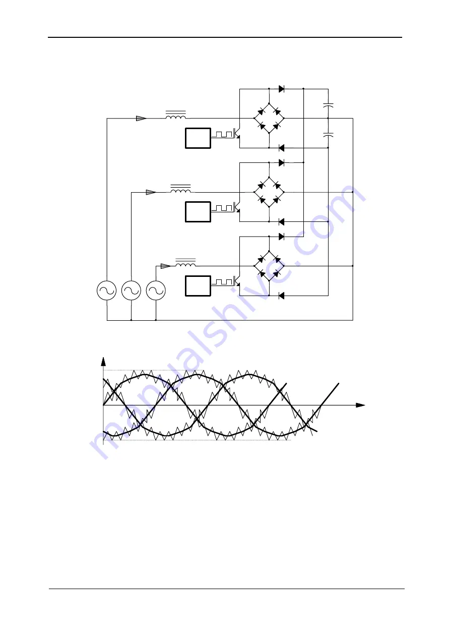
The PFC power section block diagram is shown in Figure 


2-3. Input currents of the PFC 

(without filters) is shown in Figure 


2-4; the control scheme is illustrated in Figure 


2-5. 

-+

T

Control

-+

+

Ir

+

Control

Is

Control

N

-+

R

S

It


Figure 


2-3:  Power section of the PFC in a single UPS module 


Ir

Is

It

(CCM)

t

-Ipeak

Ipeak


Figure 


2-4:  Input currents of the PFC (without filters) 

As shown in Figure 


2-3, the PFC section operates in Continuous Current Mode (CCM) 

conduction, which has many advantages. Input currents are shaped in such a way that they 
follow the input voltages with precision. 
This makes the system appear to be nothing more than a resistive load with respect to the line 
voltage. In other words, the system corrects the input current waveform of the connected load, 
and acts as an active power filter. 
The PFC section also draws symmetrical currents from each phase, and maintains good 
current sharing among identical UPS modules in parallel. 

Each phase input is sensed for voltage and current, required to force the input current drawn 
from the phase input to follow its voltage and emulate a resistor. Two feedback loops are 

Содержание POWER PLUS

Страница 1: ...588 8222 Fax 972 2 582 8875 Email info gamatronic co il Website www gamatronic com P PO OW WE ER R M Mo od du ul la ar r U UP PS S s sy ys st te em m 1 10 0 k kV VA A t to o 1 10 00 0 k kV VA A 3 3x...

Страница 2: ...ormation contained herein for any purposes other than those for which it was disclosed is strictly forbidden Gamatronic Electronic Industries Ltd reserves the right without prior notice or liability t...

Страница 3: ...helf Address 36 3 9 F A Q Frequently Asked Questions 39 3 9 1 Batteries 39 3 9 2 General 40 3 9 3 Menus 41 3 9 4 Installation 42 3 9 5 Mechanics 43 3 9 6 Common problems 43 4 SYSTEM INSTALLATION 45 4...

Страница 4: ...ation Factor for Alarms 86 11 1 3 Auto Test Batteries 86 11 2 Setting Password Level 1 86 11 3 Adding a POWER module 87 11 4 System Controller setup verification 88 11 4 1 ACCESS 88 11 4 2 SCREEN 1 88...

Страница 5: ...tem Modular structure 15 Figure 3 2 Schematic of a 3 1 Phase 30kVA POWER System 16 Figure 3 3 Schematic of a 3 Phase 30kVA POWER System 17 Figure 3 4 POWER System Rear View 18 Figure 3 5 Control PCB a...

Страница 6: ...60 Figure 5 14 Controller menu 2 61 Figure 5 15 Controller menu 3 61 Figure 5 16 Controller menu 4 61 Figure 5 17 Number of UPS modules 61 Figure 5 18 Log display 62 Figure 6 1 40kVA N 1 System with I...

Страница 7: ...Calibrating battery current measurements 98 Table 14 1 Time displays 100 Table 14 2 Main dip switch statuses 100 Table 14 3 Panel and slave dip switch statuses 101 Table 14 4 Controller external and i...

Страница 8: ...THOUT A NEUTRAL NULL CONDUCTOR FAILURE TO USE A NEUTRAL CONDUCTOR MAY CAUSE PERMANENT DAMAGE TO THE SYSTEM IN THE EVENT THAT SYSTEM OUTPUT CAPACITY IS INCREASED ABOVE THE ORIGINAL FACTORY CONFIGURATIO...

Страница 9: ...E The Power is a parallel redundant UPS A block diagram is shown in Figure 1 1 below UPS 10KVA UPS 10KVA Static Switch RS232 TCP IP Cellular Centralized UPS 10KVA Mains Power Output Isolation Transfor...

Страница 10: ...echnical Guide The system comprises the following sub assemblies 1 10 UPS modules 10kVA 4 in the example in Figure 1 2 below System Controller Static Switch Module Power Distribution Block Figure 1 2...

Страница 11: ...Gamatronic Electronic Industries Ltd Power Technical Guide 3 Figure 1 4 50kVA configuration Figure 1 5 100kVA configuration...

Страница 12: ...to a stable 425V at the DC link This stage can maintain current sharing between the three input phases as well as among other parallel units because of the current sharing signal that it produces Fig...

Страница 13: ...Gamatronic Electronic Industries Ltd Power Technical Guide 5 Figure 2 2 Block diagram of a single UPS Module...

Страница 14: ...t Mode CCM conduction which has many advantages Input currents are shaped in such a way that they follow the input voltages with precision This makes the system appear to be nothing more than a resist...

Страница 15: ...ier current to follow the phase input voltage The output of the integrator is connected to a current sharing bus causing all other modules to be connected to this bus via the same resistor This ensure...

Страница 16: ...system The POWER inverter uses Insulated Gate Bipolar Transistors IGBT as efficient high frequency switches Apart from the AC DC PFC and DC AC inverter each UPS module also contains a digital controll...

Страница 17: ...5 Output Voltage V 3 400 N 3 230V Output Static Regulation 1 Output Regulation for unbalanced load 1 for 100 unbalanced load Dynamic response to 100 load step 2 110 for 10 minutes 125 for 60 seconds O...

Страница 18: ...s include temperature compensation of the battery voltage The POWER can work without the system controller but with reduced functionality Figure 2 8 shows the system controller block diagram The core...

Страница 19: ...Gamatronic Electronic Industries Ltd Power Technical Guide 11 Figure 2 8 System controller Block diagram...

Страница 20: ...abnormal DC abnormal UPS module s failure Load on bypass Battery test failed Over under temperature Overload RTC operation without power 2 weeks Power requirements 12V 10 1A via 2 1mm phono jack 2 3 S...

Страница 21: ...Gamatronic Electronic Industries Ltd Power Technical Guide 13 Figure 2 9 ST SW front panel view Figure 2 10 ST SW block diagram...

Страница 22: ...Gamatronic Electronic Industries Ltd 14 Power Technical Guide BP BP BP INV INV Monitoring Control B INV Outputs Figure 2 11 3 Phase ST SW block diagram...

Страница 23: ...own in Figure 3 1 A major advantage of the POWER is its upgradability simply by adding UPS modules and shelves as required The system controller occupies the same space as the UPS module and although...

Страница 24: ...er system are illustrated in schematics in Figure 3 2 single phase output and Figure 3 3 3 phase output below Figure 3 2 Schematic of a 3 1 Phase 30kVA POWER System Note For use with single phase inpu...

Страница 25: ...les are routed between the UPS modules system controller and static switch down to the AC and DC distribution sections that are mounted at the bottom of the rack Figure 3 1 shows the rear view of the...

Страница 26: ...Gamatronic Electronic Industries Ltd 18 Power Technical Guide Figure 3 4 POWER System Rear View...

Страница 27: ...es This flat cable is connected to a small PCB in the UPS shelf and is connected to the control DIN48 connector described on page 24 NOTE PROPER CONNECTION OF THE FLAT CABLE IS OF CRITICAL IMPORTANCE...

Страница 28: ...three phases This can result in serious damage to the UPS A 4 pole switch might disconnect the neutral line WARNING If you have a mains to generator four pole switching system you are in danger of hav...

Страница 29: ...Gamatronic Electronic Industries Ltd Power Technical Guide 21 Figure 3 6 Wrong way to connect UPS with grounded neutral generator...

Страница 30: ...Gamatronic Electronic Industries Ltd 22 Power Technical Guide Figure 3 7 Acceptable connection for grounded generator and 4 pole switch...

Страница 31: ...Gamatronic Electronic Industries Ltd Power Technical Guide 23 Figure 3 Figure 3 8 Preferred generator neutralized and connection 3 pole...

Страница 32: ...d control WARNING ALL THE CONNECTOR PINS CARRY HAZARDOUS VOLTAGES ALWAYS AVOID ACCESS TO THESE PINS Input Connector 15 Pin DIN Control Connector 48 Pin DIN Output Connector 15 pin DIN Figure 3 9 UPS m...

Страница 33: ...C 22 Neutral 24 Neutral 26 Neutral 28 N C 30 N C 32 N C Control Connector a Column b Column c Column 1 System Controller Com 1 Controller TX 1 Controller RX 2 Dry2_opto_E 2 N C 2 N C 3 Dry2_opto_C 3...

Страница 34: ...tion panel is located at the bottom of the system on the rear below the first UPS module UPS 1 This panel receives the DC wires from the system s UPS modules and from the controller as well as from in...

Страница 35: ...Gamatronic Electronic Industries Ltd Power Technical Guide 27 Figure 3 11 DC distribution panel 50KVA model Figure 3 12 DC distribution panel 100kVA model...

Страница 36: ...nt side of the DC distribution panel There are two fuses for each power module and for the controller one for the positive line and one for the negative line Figure 3 13 and Figure 3 14 show the assig...

Страница 37: ...e controller has 3 fuses for R S T phases 10 modules plus the controller would require 33 fuses as illustrated in Figure 3 15 Fuse receptacles are numbered from right to left i e the 3 fuses on the fa...

Страница 38: ...butes AC voltages to and from the UPS modules and is located on the rear of the UPS below the DC distribution panel Connections are as shown below The AC input to the modules are protected by the AC f...

Страница 39: ...m installation The terminals are used to connect the AC inputs and AC output to the mains electricity cabinet The terminals section is illustrated in Figure 3 20 The installation procedure is detailed...

Страница 40: ...are located accordingly on top of the unit A separate terminal is dedicated for the Neutral line which does not carry current and is used for measurements This module communicates with the rest of the...

Страница 41: ...r outside the shelf Rear view 3 7 1 PC714 THE CONTROLLER CARD The PC714 card contains the logic chips that perform the UPS controller functions PC714 also contains the LCD display screen and several j...

Страница 42: ...Gamatronic Electronic Industries Ltd 34 Power Technical Guide Figure 3 23 Front side of PC714 card Figure 3 24 Rear of PC714 white rectangle indicates jumper area Figure 3 25 The jumpers on PC714...

Страница 43: ...ce a capacity from 10 to 890 amp hrs can be specified When the jumper is removed a capacity from 10 to 89 amp hrs can be specified JP4 JP5 These two jumpers should normally always be in place When in...

Страница 44: ...ddress is related to the physical location of a specific shelf and is preset at the factory by the Module Location DIP switch mounted on the control PCB See Figure 3 26 When adding a new module to an...

Страница 45: ...the PC719 card which is located on the back of each shelf housing a UPS or the controller module Master Slave DIP Switch Settings The two DIP switches on the left determine which UPS will be the maste...

Страница 46: ...cating UPS 1 See Table 3 3 below and FIGURE 3 29 Table 3 3 DIP switch setup in a 100kVA system X don t care Figure 3 29 DIP switch settings Lowest Module Select LMS jumper The first module UPS 1 must...

Страница 47: ...APACITY WAS NOT SETUP CORRECTLY A Accurate values of Ah battery capacity should be entered otherwise the reliability of the smart battery test will be lower 3 9 1 4 Q WHY DOES MY BATTERY TEST LAST FOR...

Страница 48: ...ETS SELECTED WILL THE UNIT ADD THE ENTERED VALUES OR DIVIDE THEM BETWEEN THE CABINETS A If the number of battery cabinets is set to more than one then you will have to select the battery Ah rating for...

Страница 49: ...If the output voltage is triple phase then the bypass input should be triple phase as well If the output is single phase and the output phases are linked altogether then the same thing should be done...

Страница 50: ...ork without a load and with batteries disconnected Then the offset removal should be preformed only if the measurement current is not zero and then the unit should be connected to some load and batter...

Страница 51: ...h 8mm or 10mm hole 3 9 4 9 Q DOES THE UNIT HAVE DRY CONTACT FOR THE LOAD ON BYPASS SIGNAL A Yes it is located on the ST SW module Unscrew two mounting screws on the front panel of the ST SW module and...

Страница 52: ...d always be set to DISABLED this feature is not available If you had it on in your system please note that it could simulate a failure condition and a shutdown to the computers On all the units today...

Страница 53: ...ide 45 4 SYSTEM INSTALLATION WARNING RISK OF ELECTRICAL SHOCK OR INJURY INSTALLATION MAY BE PERFORMED BY QUALIFIED TECHNICIAN ONLY Figure 4 1 illustrates the cabling of the POWER system to the mains e...

Страница 54: ...ion For battery connections see Figure 6 3 on page 68 Figure 4 2 Switch and wire ratings for 10 100kVA installation POWER 400 V MODEL UPS OUTPUT CAPACITY KVA S2 S6 AND RA101 AMPS WIRES mm2 RA101 OPTIO...

Страница 55: ...for cable connections and 100cm at front for user access and service 6 Circuit breakers on the electrical board supplying the system Must be in accordance with Gamatronic system specifications and co...

Страница 56: ...s to the UPS terminals according to markings as shown in Figure 4 1 on page 45 and Figure 6 3 on page 68 Connect neutral and ground lines to busses as above Verify correct polarity of the connections...

Страница 57: ...to initialize When applying power to the POWER the system automatically runs the startup process without a need to press the On Off button The start up sequence will begin and the control panel will s...

Страница 58: ...red in item 5 below 2 With no load on the system measure current circulation between the units Irst should be 15 A 3 With no load on the system measure the DC voltage of the system Total DC voltage be...

Страница 59: ...system measure the DC voltage of the system Total DC voltage between and terminals should be between 850V and 880V R S T 11 Voltage between neutral and ground during operation under load On the input...

Страница 60: ...n dip switch no 3 is set to ON LEFT position 3 For single phase output 3 1 or 1 1 configuration set the dip switch no 3 to OFF RIGHT position on all of the modules of the System 4 5 2 WIRING OF INPUT...

Страница 61: ...cording to the System configuration Table 4 1 Power Configuration DIP Switch Settings Switch Purpose Set left on Set right off SW1 Master module preference Preferred master select not used Automatic v...

Страница 62: ...eration in stand alone mode y Dip switch 2 in middle should be ON LEFT for 60Hz and OFF RIGHT for 50Hz inverter operation y Dip switch 3 in top should be ON LEFT for 3 phase and OFF RIGHT for 1 phase...

Страница 63: ...eneral information such as voltages currents etc UPS Information for a specific UPS module SELFTEST Self checking of the Controller s components supply RTC memory HISTORY History log events last 255 e...

Страница 64: ...td 56 Power Technical Guide 5 1 SYSTEM INFORMATION DISPLAY Figure 5 2 Main menu option 1 System The SYSTEM option on the Main Menu option 1 shows the DC voltages and current positive negative and summ...

Страница 65: ...oll down again to see accumulated operation time and duration of current session Figure 5 7 General timers and counters 2 1 kVA is 1000 VA Apparent power is measured in VA which is a reactive i e a mi...

Страница 66: ...See section 3 7 1 beginning on page 33 for more information about jumpers 1 2 3 6 and 9 on PC714 See Section 6 2 1 2 on page 69 for instruction for setting the battery capacity 6 Pressing the down ar...

Страница 67: ...The message shown in Figure 5 11 appears 2 Use the and keys to scroll between UPS modules The display shows the voltage and current measurements for each module see Figure 5 12 on page 60 3 Scroll an...

Страница 68: ...Technical Guide Figure 5 11 LCD Panel Selection Figure 5 12 and Figure 5 13 show parameters for the first module of a UPS system with four modules UPS 01 04 Figure 5 12 Module phase voltages currents...

Страница 69: ...enu 2 Select 7 SETUP Figure 5 1 3 Enter the password and press Ent default password is 8 x 4 Select 8 Service Figure 5 14 5 Select 5 Configure Figure 5 15 6 Select 2 of UPSs Figure 5 16 7 Set the numb...

Страница 70: ...ssage logged Data Dc voltage between and terminals for all events except LOADBP For LOADBP the field holds the STSW status See Table 5 4 below for interpretation of STSW status codes IN or OUT IN star...

Страница 71: ...charged to shutdown limit 12 BATLOW Low battery voltage 13 STSWRN Static Switch Warning or alarm 14 E P O Emergency Power Off is active 15 EQ HST Battery is currently charging in equalizing mode dc vo...

Страница 72: ...tage blackout for 3 ms 2 Inverter peak voltage 185 V brownout 4 Inverter peak voltage high 185 V brownout 8 Frequency beyond limits 45 65 Hz 16 Inverter average voltage low 32 Inverter average voltage...

Страница 73: ...currently charging in equalizing mode dc voltage is temporarily increased LOADBP Load is now running on bypass OUTFLT No AC output to load OVLOAD Load current is high OVTEMP Excess temperature SLFFLT...

Страница 74: ...tails on battery cabinet wiring and connections 6 1 1 INTERNAL BATTERIES Up to 3 internal packs each containing 64 12v 5Ah batteries may be housed in the Power system cabinet This would provide 4 minu...

Страница 75: ...tery cabinets 6 2 INSTALLING AND CONNECTING THE BATTERIES As shown in the diagram the DC output cable from the batteries is connected directly to the small Anderson connectors on the UPS rear panel WA...

Страница 76: ...Gamatronic Electronic Industries Ltd 68 Power Technical Guide Figure 6 3 Connection diagram for external battery...

Страница 77: ...ress Ent 3 Enter the system password the default password is eight left arrows press Ent 4 Select Service press Ent 5 Select Configure press Ent 6 Select of Batteries press Ent 7 Use the up and down a...

Страница 78: ...own in Figure 7 1 labeled A and B Figure 7 1 Location of dry contacts at rear of POWER controller module Figure 7 2 Dry Contacts group A as per Figure 7 1 INPUTS DRY CONTACT DESCRIPTION NAME IN ALARM...

Страница 79: ...3 Dry Contacts group B as per Figure 7 1 To install the temperature sensor connect the sensor according to Figure 7 3 and Figure 7 1 To see the temperature reading a configuration change must be made...

Страница 80: ...UPS and batteries are in proper electrical and physical condition y The operation of the UPS and its batteries conform to design specifications y The UPS and batteries are in compliance with all rele...

Страница 81: ...____________ _______________________________ Date ___________________ Signature ___________________________ Visual Inspection OK Not OK Comments _______________________________________________________...

Страница 82: ...back to front Done Return the modules and transfer the UPS back to Inverter mode Verify that the UPS functions normally Software Version Check the software version in the System Controller If it is no...

Страница 83: ...r of 0 5 300 W rating recommended for the load to check the voltage drop across the terminals of each battery There should be no more than a 10 Vdc drop for any battery Replace any batteries that seem...

Страница 84: ...an also signal a malfunction Figure 9 1 UPS module front panel As shown in Figure 9 1 there are three LEDs on the front panel of each UPS module Alarm Output and Line The internal buzzer in the UPS mo...

Страница 85: ...Off High Input Current Blinks On On Vdc 450V On Off Off High Vdc Vdc 500V On Off On Very high Vdc DC imbalance On On Blinks Low Vdc 360V On On Blinks Vdc very low 320V On Off On DC critical fail 200V...

Страница 86: ...vidually 4 Contactor sounds can be heard from the unit from time to time but no transfers to bypass have been registered These units have internal synchronization contactor which should protect from s...

Страница 87: ...orking normally but the system controller is off 1 Check AC fuses located on the rear side of base unit above the AC terminals and DC fuses located behind a blank cover above the ST SW module 2 Replac...

Страница 88: ...ontrol of the system The SCC provides communication with a wide range of management equipment such as computers and mobile phones 10 2 SCC POWER CHARACTERISTICS The controller s main functions include...

Страница 89: ...on of the software y Change communication settings y Restart the controller y Restart the network adapter 10 4 1 START UP SCREENS The welcome screen is displayed for a few seconds when the controller...

Страница 90: ...screens displaying detailed information about all aspects of the system there are seven Fast Information screens that contain further details about the real time status of the system These screens can...

Страница 91: ...A filled circle indicates an active fault y An empty circle indicates an inactive fault General Information Screen The following table describes the information displayed on the Information screen Tab...

Страница 92: ...onitoring the status of individual components of the system The Main Menu functions are listed in Table 10 2 below Table 10 2 Main Menu functions Screen Description 0 SYSTEM Monitoring the System 1 UP...

Страница 93: ...ng off alarms for the parameters of system components An alarm is set off each time a parameter value is outside the defined range of permitted values Press the number that appears beside a menu optio...

Страница 94: ...R ALARMS The integration factor is the coefficient that determines the number of times an alarm must occur before the controller records it The smaller the value of the coefficient is the sooner the w...

Страница 95: ...3 on page 38 Updating the number of modules in the Power Plus processor Ent represents a press of the Ent key Ent Setup Ent Password default password is 8 left arrows Ent Service Ent Configure Ent To...

Страница 96: ...th optional battery current sensor f T C 2 0mV negative temperature coefficient of the battery DC voltage in mV per C per battery cell Nominal temperature is 25 C For DC nominal voltage 432V temperatu...

Страница 97: ...cations g CURR SENSOR DIS or EN Optional battery current sensor is disabled enabled In most applications must be DIS 11 4 4 SCREEN 3 To access SCREEN 3 press the key ARROW RIGHT when SCREEN 2 is selec...

Страница 98: ...he system might switch to bypass due to overload of the remaining UPS modules To insert a UPS module in to the system 1 Insert the module firmly in to the housing and slide it in until it stops 2 Scre...

Страница 99: ...e available while the system controller is removed battery test battery conditioning systems etc To insert a system controller module in to the system 1 Confirm that the rear cables plugs if any will...

Страница 100: ...its terminal E 1 earth wire from a dedicated screw 4 Pull the ST SW module out from the system WARNING This operation is not possible to perform live without load and Power system disconnection The sy...

Страница 101: ...C575 which is located on PC714 see Figure 12 1 Pull out PC575 Figure 12 1 PC575 1 4 Take a PLCC extractor or a very small screwdriver and pull out the old EPROM see Figure 12 2 Figure 12 2 Extracting...

Страница 102: ...ess ENT 2 2 Select 7 SETUP 2 3 For the password press left arrow button 8 times and then ENT 2 4 Select 8 Service 2 5 Select 5 Configure 2 6 Select 5 Dry Alarms 2 7 Select 7 Enable Disable Alarms 2 8...

Страница 103: ...down or activation via a command from the controller y Adding an integration coefficient to the alarm activation criteria y System configuration y Calibration of the system s voltage and current measu...

Страница 104: ...ctory default settings 3 Network Sets the controller s network addresses 4 Reset MBX Resets the controllers network card 5 MBX SW Upgrade Prevents the network card from resetting while the card is bei...

Страница 105: ...one dry contact and a dry contact can be linked to more than one alarm 13 4 2 ENABLING AND DISABLING SPECIFIC ALARMS An alarm can be disabled or enabled as follows 1 Main menu Setup Password Service m...

Страница 106: ...ts including the controller s main card and the internal voltage DC DC supply unit are functioning correctly The self test is performed either automatically at midnight or following controller activat...

Страница 107: ...of the batteries y System temperature y Communication status Figure 14 1 Key panel 14 1 POWER METER The Power UPS contains a built in digital power meter allowing you to monitor the line supply the l...

Страница 108: ...t 19 33 58 When the system was last restarted Previous Controller Session Duration of the previous session HH MM SS YYYY MM DD When the last session began and ended format hours minutes seconds year m...

Страница 109: ...W Flash is upgradable Read Write chgbl It is possible to switch the active Flash memory Changeable noecH No echo when the slave contacts the communication board 14 5 SC POWER INTERNAL POWER SUPPLY Ta...

Страница 110: ...ns displaying data about the controller P D dialog y Screens displaying information about the dialog between the controller and the rectifiers There is a screen for each rectifier in the system y Scre...

Страница 111: ...the battery test progress and the status of the last battery test 14 8 1 1 BATTERY TEST PROGRESS Table 14 6 Battery test information INFORMATION DESCRIPTION Max Estim Time Left Maximum or estimated ti...

Страница 112: ...detailing the dependency of each dry contact to the alarms y Six screens showing the relationship of the LED lights which can be user programmed to the alarms y Four screens corresponding to the alar...

Страница 113: ...ad CF max 6 1 AC AC efficiency nominal Up to 96 at full load DC AC efficiency nominal Up to 98 at full load Batteries DC Link Voltage V 340 to 425 Quantity 64 12 V Type Sealed lead acid rechargeable G...

Страница 114: ...PP 2U 3Kg 2 UPS MODULE 10KVA 10110033H PP 2U 9 5Kg 3 HOUSING UPS and CONTROLLER 101H PP 2U 6Kg 4 DC AC DISTRIBUTION and BASE 50KVA 101B050 PP 11U 40Kg 5 DC AC DISTRIBUTION and BASE 100KVA 101B100 PP 1...

Отзывы: