background image


Version 1, 15 June 2020, 7 of 16 


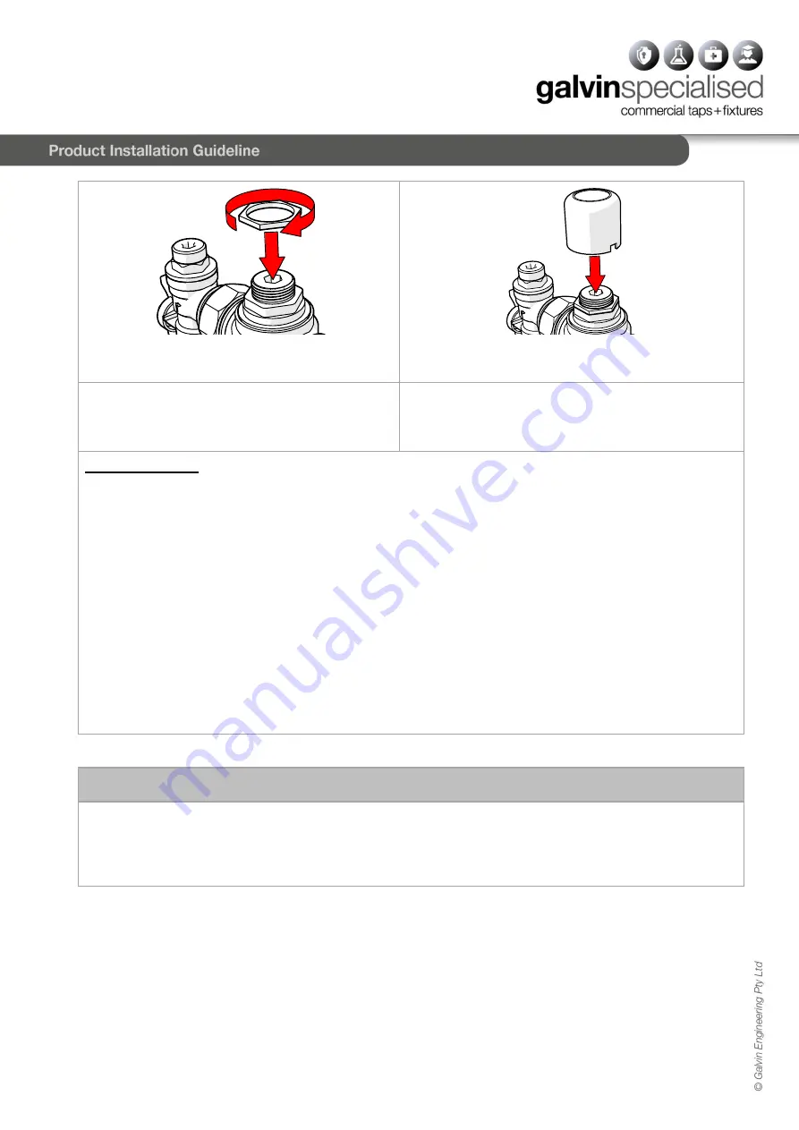
5.  Retighten the Temperature Locking Nut with and 

adjustable spanner 

6.  Push the top cover firmly on to the top of the valve until 

is ‘snaps’ back into place. 

7.  Check the outlet temperature is stable over a full 

range of flow rates and that the flow rate is 
adequate for the application. 

8.  Close the outlet.  The TMV is now set and locked. 

SHUT DOWN TEST 

Now that the TMV has been set and locked it is necessary to perform a shutdown check.  Allow the mixed water 
temperature to stabilize and note the outlet temperature. While holding a digital thermometer in the outlet flow, 
quickly isolate the cold water supply to the valve. The outlet flow should quickly cease flowing. As a rule of thumb 
the flow should be less than 0.1L/min following the isolation. Monitor the maximum outlet flow temperature, and 
record this on the Commissioning Report (Appendix A). The temperature should not exceed that allowed by the 
applicable standard or code of practice for each state and territory. Restore the cold water to the TMV. After the 
mixed  water  temperature  has  stabilized  note  the  outlet  temperature  ensuring  the  outlet  temperature  has 
reestablished. 

Now repeat the above test, except this time quickly isolate the hot water supply to the valve. The outlet should 
quickly slow to a trickle. As a rule of thumb, the trickle should typically be less than 0.4L/min @ 500kPa down to 
less than 0.1L/min @ 100kPa following the isolation. Restore the hot water supply to the valve and measure and 
record the outlet temperature has stabilized ensuring the outlet temperature has reestablished. 

Ensure that all details of the Commissioning Report are completed and signed by the relevant signatories. A copy 
of this report should be kept with the installer and owner of the premises. 

The valve is now commissioned and it can be used within the technical limits of operation.


8.0  

MAINTENANCE AND SERVICING


The Galvin Engineering CliniMix

®

 Thermostatic Mixing Valve will only require minimal preventative maintenance 

work to ensure it operates at its optimum level of performance. The valve should be commissioned and serviced 
annually, unless the installed conditions dictate more frequent servicing is necessary.


Содержание 101.10.70.10

Страница 1: ...ng tempered water to the desired outlets This stainless steel hinged cabinet kit is a lockable cabinet with 20mm copper fittings 2 in and 1 out which allows secure installation and safe simple mainten...

Страница 2: ...es 3 0 DESCRIPTION This manual covers the CliniMix Lead SafeTM TMV SS Cabinet Assembly with Universal Door 20 Bottom In Out These are designed to provide tempered water to the desired outlets This mix...

Страница 3: ...APH The Galvin Engineering CliniMix Thermostatic Mixing Valve is suitable for many applications The Head loss Characteristic for Mixed Outlet Flow rate versus Balanced Inlet Pressure is shown below in...

Страница 4: ...ction within specification on unequal pressures up to 6 1 The mixer has integral isolating valves which permit servicing of the strainer check valve flow regulator and thermostatic cartridge They are...

Страница 5: ...ure to do this may void the warranty 3 Connect water lines Before connecting to water lines all lines must be flushed Remove protective vinyl cap from copper tubes Join each copper tube to the correct...

Страница 6: ...rtest length of pipe work between the mixing valve and outlet fixture Allow the mixed outlet to flow for at least 60 seconds to allow the temperature to stabilise before taking a temperature reading a...

Страница 7: ...Restore the cold water to the TMV After the mixed water temperature has stabilized note the outlet temperature ensuring the outlet temperature has reestablished Now repeat the above test except this t...

Страница 8: ...st plugs in the top of the inlet fittings are tight and that there is no evidence of water leakage The TMV must then be recommissioned as per Section 7 0 including temperature adjustment and the shutd...

Страница 9: ...rass top assembly screw out the plastic spindle and replace the smaller O ring 5 Carefully remove the spindle from the center of the body 6 Remove O ring from spindle Replace with O ring supplied in t...

Страница 10: ...OR WM TMV1 1 2 WM ISO 1 INLET ISOLATOR ELBOWS PAIR FOR WM TMV1 1 3 WM NRV 1 INLET NON RETURN VALVE FOR WM TMV1 PAIR 1 4 WM STR 1 INLET STRAINERS FOR WM TMV1 PAIR 1 5 WM TPKIT 1 THERMOSTAT PISTON SHUTT...

Страница 11: ...r s recommendation the ode and all relevant statutory and local tate or erritory requirements 4 The TMV must be returned to Galvin Engineering together with a fully and correctly completed Galvin Engi...

Страница 12: ...ntrol valves to ensure inlet conditions are within range Clean strainers ensuring debris is removed Either full hot or cold flowing from the outlet fixture Valve is incorrectly set Hot Cold water has...

Страница 13: ...___________________ Model No ________________________ Size _________ Valve Location Building _____________________________________________________________________ Valve Identification No _____________...

Страница 14: ...k It is hereby certified that all the commissioning work has been carried out by the undersigned in accordance with the requirements of the Codes of Practice indicated prior Date of Valve Commissioned...

Страница 15: ...Outlets in Use One Outlet in Use All Req d Outlets in Use 1 2 3 4 5 6 7 8 9 10 11 Give details of brand and model designation Commensurate with the design flow rate for the mixing valve Note An accura...

Страница 16: ...e ______________________ Date _______________________ Maintenance Tests Yes Date of Previous Service ______________________________________________________________________ Previous Service carried out...

Отзывы: