background image

13

SY66000058  -  0

3

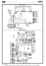
MS

MS

MS

MS

MS

È severamente vietata la riproduzione anche parziale di questo manuale / All copying, even partial, of this manual is strictly forbidden

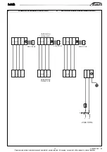
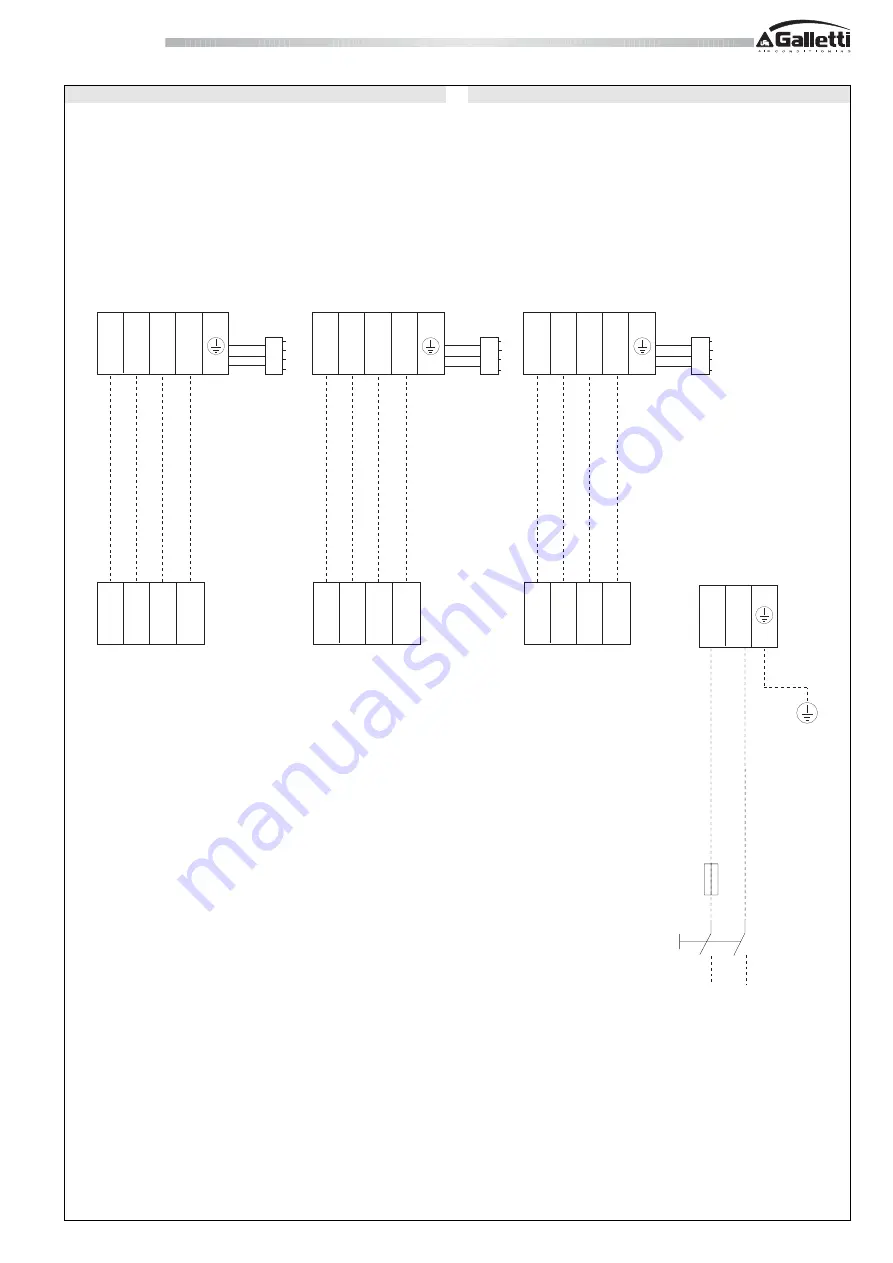
1 2(N) 3

4

1 2(N) 3

4

1 2(N) 3

4

230V 50 Hz

230V 50 Hz

230V 50 Hz

Unità interna

Indoor unit

Unità esterna

Outdoor unit

L

N

L

N

230V 50 Hz

F

IL

1 2(N) 3

4

1 2(N) 3

4

1 2(N) 3

4

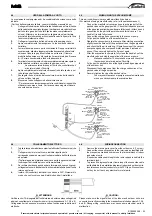
4.7

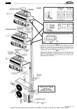
SCHEMA DI COLLEGAMENTO TRA LE UNITÀ

4.7

ELECTRICAL CONNECTIONS BETWEEN THE UNITS

Содержание MS 999 H

Страница 1: ...I GB Manuale di installazione e manutenzione Installation and maintenance manual MS 999 H MS 9912 H Multisplit con unit interne a parete alta Multisplit with high wall indoor units...

Страница 2: ...on 10 4 5 When using the vacuum pump 11 4 6 Wiring connection 11 12 4 7 Electrical connection between the units 13 4 8 Wiring diagram legend 14 4 9 Water tray installation 14 4 10 Gas leak check 14 4...

Страница 3: ...di manutenzione devono essereeffettuatidapersonalequalificato salvodiverseindicazioniriportate in questo manuale Prima di effettuare qualsiasi intervento sulla unit togliere tensione alla macchina Ilm...

Страница 4: ...DENOMINAZIONE 1 piastra di fissaggio 2 Vite di montaggio A ST3 9x25 C H 3 Tassello a espansione 4 Comando a distanza 5 Vite di montaggio B ST2 9x10 C H 6 Supporto per comando a distanza 9 Vite di mon...

Страница 5: ...come identificatoconirispettivinumeridiaccoppiamentoA1 A2eBpostisull unit esterna Terminato il collegamento le unit interne debbono essere contrassegnate rispettivamente con i numeri A1 A2 e B NOTE C...

Страница 6: ...UN FORO E MONTARE LA PIASTRA DI FISSAGGIO 3 3 1 Praticare un foro Quando la tubazione viene collegata dalla parte posteriore Stabilire la posizione del foro per il tubo utilizzando una piastra di fis...

Страница 7: ...re tasselli a espansione 3 4 INSTALLAZIONEDELL UNIT INTERNA 1 Far passare il tubo attraverso il foro praticato nella parete 2 Inserire la forcella superiore nella parte posteriore dell unit interna su...

Страница 8: ...parecchio 2 Non allungare il cavo elettrico tagliandolo Sezione mm Corrente nominale A 3 6 0 75 6 10 1 10 16 1 5 16 25 2 5 25 32 4 32 40 6 40 63 10 ATTENZIONE Eseguire i collegamenti elettrici con pot...

Страница 9: ...ubo e svasarlo LEFT HANDORREAR LEFT HANDPIPING 1 For the left hand piping remove the rear plate bushing from the left side of the rear plate Explain to clients that the rear plate bushing must be kept...

Страница 10: ...omito ad un tubo flessibile di prolunga da acquistare sul posto 4 2 TIGHTENINGCONNECTION Alignpipestobeconnected Sufficientlytightentheflarenutwithfingers and then tighten it with a spanner and torque...

Страница 11: ...chiuse del tubo lato gas e del tubo lato liquido siano completamente chiuse Attaccare un terminale di collegamento sul particolare provvisto di protuberanza per il nucleo della valvola Il pomello Hi v...

Страница 12: ...12 SY66000058 03 MS MS MS MS MS severamente vietata la riproduzione anche parziale di questo manuale All copying even partial of this manual is strictly forbidden MI 999 9912 H MO 999 9912 H...

Страница 13: ...copying even partial of this manual is strictly forbidden 1 2 N 3 4 1 2 N 3 4 1 2 N 3 4 230V 50 Hz 230V 50 Hz 230V 50 Hz Unit interna Indoor unit Unit esterna Outdoor unit L N L N 230V 50 Hz F IL 1 2...

Страница 14: ...ACITOR VENTILATORE CONDENSATORE ESTERNO CAP2 OUTDOOR COMPRESSOR CAPACITOR COMPRESSORE CONDENSATORE ESTERNO XT3 XT7 MIDDLE TERMINAL CONNETTORE CENTRALE XT1 3 WAY TERMINAL CONNETTORE A 3 VIE XT8 XT10 5...

Страница 15: ...collegamenti con dadi svasati Per funzionamento in raffreddamento Portarel interruttoreTEMPORARY temporaneo suCOOL freddo SISTEMA DI PROTEZIONE DI 3 MINUTI Unsistemadiprotezioneimpediscealcondizionat...

Страница 16: ...easuresif necessary Connectthegroundingwireto the air conditioner EXPLANATION Suitable location a Place that is always dank b Hard soil rather than loose sandy soil Unsuitable location a Where there a...

Отзывы: