background image


Page


46


of


56


RG66006951

Rev.01


3.3 

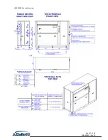
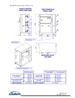
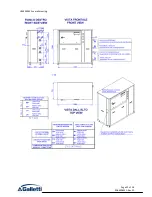
Overall drawings of optional hydronic modules 


HF64000799


overall


drawing


Содержание LEW CD

Страница 1: ...GB Technical manual LEW Reversible Chillers and Heat Pumps LEW SERIES 40 420 kW ...

Страница 2: ...Page 2 of 56 RG66006951 Rev 01 ...

Страница 3: ...ONENTS 14 1 4 ELECTRIC PANEL 18 1 4 1 CONTROL MICROPROCESSOR 18 2 MAIN UNITS TECHNICAL DATA 19 2 1 PERFORMANCE OF LEW C D H W HEAT PUMP UNITS 25 2 2 NOISE EMISSION 28 2 3 OVERALL DIMENSIONS AND WEIGHT OF THE MAIN UNITS 28 2 4 OVERALL DRAWINGS OF THE MAIN UNITS 30 3 TECHNICAL DATA OF OPTIONAL HYDRONIC MODULES 39 3 1 CHARACTERISTIC CURVES OF THE HYDRAULIC PUMPS ASSOCIATED TO THE UNITS 39 3 2 OVERALL...

Страница 4: ...Page 4 of 56 RG66006951 Rev 01 Declaration of conformity The declaration of conformity is attached to each machine ...

Страница 5: ...n the table below The sizes of the LEW units are expressed in the X coordinates of the table in terms of rated cooling capacity kW obtained in conditions with chilled water produced at 7 C and combined with the evaporative turret with dissipation circuit water at 29 inlet and 35 outlet Table I Table summarising the range of LEW products by size and Efficiency Pack Sizes 040 050 060 070 080 090 110...

Страница 6: ...uit breakers 2 2 control microprocessor and expansion device CMP2 base electronic expansion valve 0 base mechanical expansion valve A programmable LCD display 8x22 electronic expansion valve B programmable LCD display 8x22 mechanical expansion valve C 3 Partial heat recovery mandatory condensation control CMP3 absent 0 de superheater 40 Pf recovered under normal circumstances D Not available if Fi...

Страница 7: ...nnection I Filter cut off kit solenoid and cock on liquid line L Outdoor temperature sensor for set point compensation M Not available if Field 2 0 A Dissipation side water temp probe for Version H or W N Not available if Field 10 1 2 1 1 3 Field of application LEW units are designed for cooling heating water and solutions containing up to 30 glycol percentage by weight in civil industrial and tec...

Страница 8: ...Chiller mode cool the water to cool down the environment on the utility side thereby dissipating condensation heat with the water cooled by the dissipation heat exchanger Heating LEW H W units in Heat Pump mode heat the water in the condenser to heat the utility side thereby dissipating the evaporation cooling capacity by means of the water which is heated in the dissipation heat exchanger In othe...

Страница 9: ...ng section of the thermodynamic unit which is at a higher temperature If only part of the heat is drawn a de superheater sends gas sensitive heat to the delivery pipe towards the third thermal source at a higher temperature Upon specific demand all cold only units of the LEW series can be equipped with a de superheater for partial heat recovery The available thermal output that can be used for dom...

Страница 10: ...sipation source It occupies less space on the floor plan specific powers up to 153 kW m2 Innovative aesthetic features and full safety since units are completely closed No noise on the outside less noise on the inside due to dual soundproofing in low noise versions 1 2 Structure All LEW series units have the load bearing base and panelling in galvanised sheet metal painted with polyester powders a...

Страница 11: ...mpared to other solutions Compressor motors are protected against overheating overloads and high delivery gas temperatures They are mounted on rubber anti vibration mounts complete with oil charge and inserted in a soundproof compartment with sound absorbing material Also complete with automatic oil heater to prevent the oil from being diluted by the refrigerant when the compressor stops NOTE Scro...

Страница 12: ... you to limit the time needed for the system to reach full operating capacity to a few moments A buffer tank must be placed between the unit and the utility since the demand for hot water and its availability are not simultaneous because it needs the compressors to be running It should be pointed out that the heat recovery output is linked to the dispensed cooling output and that therefore in part...

Страница 13: ...ing circuit operation very efficient stabilising and decreasing the power absorbed by the system when a sudden thermal load variation occurs The shutter in the central part of the valve can always slide vertically with an ample stroke allowing variation of the degree of opening of the orifice of the fluid passage Using this valve reduces compressor energy consumption when the surrounding condition...

Страница 14: ...r dryer Sight glass with humidity indicator One way valves only reversible heat pump Liquid receiver marked in compliance with EC Directive 97 23 PED only reversible heat pumps or units with remote condenser High and low pressure switches Schrader valves for control and or maintenance ...

Страница 15: ...G66006951 Rev 01 Diagram of the dual circuit cold only version please note this is a standard layout refer to the layout enclosed with the unit To consult the layouts please refer to the symbols in the following table ...

Страница 16: ...Page 16 of 56 RG66006951 Rev 01 Diagram of the dual circuit reversible heat pump version please note this is a standard layout refer to the layout enclosed with the unit ...

Страница 17: ...Page 17 of 56 RG66006951 Rev 01 Reference table for numbering used in layouts ...

Страница 18: ...ote control remote consents are implemented by very low voltage contacts placed on the terminal board 1 4 1 Control microprocessor LEW series units have two different microprocessor control levels Basic Carel µChiller Advanced Carel series pCO The latter in addition to the functions described below can customise the software to meet all system requests These include cascade management of the units...

Страница 19: ...46 0 50 0 50 0 Booster current LRA A 111 0 111 0 156 0 156 0 157 0 157 0 164 0 164 0 176 0 176 0 LRA with soft starter kit A 73 0 73 0 83 0 83 0 102 0 102 0 107 0 107 0 117 0 117 0 EER 5 75 6 05 5 46 5 45 5 72 5 73 5 54 5 54 5 76 5 76 Refrigerant load kg 6 5 6 5 6 6 7 7 7 7 RATED TECHNICAL DATA OF LEW WATER CHILLERS 12 7 C 15 30 C Efficiency pack 1 2 1 2 1 2 1 2 4 LEW CS CL 91 92 111 112 131 132 1...

Страница 20: ... EER 5 53 5 54 5 59 5 46 5 47 5 54 5 64 5 55 Refrigerant load kg 15 15 15 16 15 22 22 22 RATED TECHNICAL DATA OF LEW WATER CHILLERS 12 7 C 15 30 C Efficiency pack 3 4 3 4 4 4 4 4 4 LEW CS CL 243 244 283 284 314 344 374 424 484 Cooling capacity kW 267 9 279 0 313 0 316 4 349 7 377 4 410 6 453 5 520 7 Rated absorbed power kW 47 8 47 9 56 4 56 3 64 7 70 4 74 5 81 6 92 5 Evaporator side pressure drops...

Страница 21: ...3 36 3 36 3 33 3 33 3 45 3 44 3 37 3 37 3 51 3 51 ESEER 5 61 6 04 5 39 5 78 5 73 6 11 5 59 6 01 5 89 6 25 Refrigerant load kg 4 4 4 5 5 5 5 6 7 7 RATED TECHNICAL DATA OF LEW WATER CHILLERS 12 7 C 40 45 C 30 glyc Efficiency pack 1 2 1 2 1 2 1 2 4 LEW DS DL 91 92 111 112 131 132 141 142 144 Cooling capacity kW 83 7 83 8 101 5 101 4 115 3 115 5 132 8 132 9 133 5 Rated absorbed power kW 24 6 24 6 28 7...

Страница 22: ... 17 6 24 5 84 6 29 6 33 6 46 6 44 Refrigerant load kg 15 13 15 16 15 22 24 27 RATED TECHNICAL DATA OF LEW WATER CHILLERS 12 7 C 40 45 C 30 glyc Efficiency pack 3 4 3 4 4 4 4 4 4 LEW DS DL 243 244 283 284 314 344 374 424 484 Cooling capacity kW 231 8 240 2 266 2 269 4 298 3 321 4 349 1 386 7 442 05 Rated absorbed power kW 63 6 65 6 75 2 75 9 86 3 93 3 100 4 109 2 126 57 Evaporator side pressure dro...

Страница 23: ...6 4 71 4 71 4 94 4 93 ESEER 5 61 6 04 5 39 5 78 5 73 6 11 5 59 6 01 5 89 6 25 H version refrigerant load kg 8 6 8 7 8 7 9 8 10 9 W version refrigerant charge kg 5 4 5 4 5 4 7 6 7 6 RATED TECHNICAL DATA OF LEW HEAT PUMPS 15 10 C 40 45 C Efficiency pack 1 2 1 2 1 2 1 2 4 LEW HS HL LEW WS WL 91 92 111 112 131 132 141 142 144 Cooling capacity kW 84 19 84 3 102 02 101 96 116 12 116 09 133 77 133 65 134...

Страница 24: ...41 31 28 42 42 43 W version refrigerant charge kg 13 12 25 15 13 25 25 27 RATED TECHNICAL DATA OF LEW HEAT PUMPS 15 10 C 40 45 C Efficiency pack 3 4 3 4 4 4 4 4 4 LEW HS HL LEW WS WL 243 244 283 284 314 344 374 424 484 Cooling capacity kW 232 74 241 14 267 41 270 57 300 02 326 54 354 46 393 07 450 32 Utility side pressure drops kPa 38 25 29 30 36 35 34 33 35 Heat sink pressure drops kPa 57 33 41 4...

Страница 25: ...66 8 27 3 158 3 30 2 149 1 33 4 178 8 23 7 178 24 176 6 24 3 15 10 149 7 24 5 148 8 24 9 147 6 25 3 143 2 26 9 135 5 30 1 127 8 33 2 153 8 23 0 152 9 23 5 150 8 24 1 10 5 128 24 1 126 9 24 5 125 9 25 122 26 7 115 4 29 9 108 8 33 131 8 22 6 130 7 23 1 128 8 23 8 LEW 141 2 20 15 201 8 28 1 201 1 28 4 199 3 28 9 191 6 31 4 180 0 34 5 171 4 38 1 204 8 27 3 203 7 27 6 202 4 28 0 15 10 173 8 27 7 172 7 ...

Страница 26: ... 5 71 7 391 6 73 4 LEW 424 20 15 578 5 84 6 574 1 85 8 568 8 87 2 550 3 93 522 4 101 8 492 9 111 8 599 9 81 1 597 8 82 1 592 5 83 4 15 10 498 8 82 1 496 1 83 3 491 4 84 7 475 5 90 4 450 5 100 0 425 4 109 6 517 8 78 5 515 5 79 8 506 2 81 7 10 5 428 3 79 6 426 4 80 6 423 2 82 407 9 88 385 8 98 0 363 6 107 9 444 5 76 1 443 77 2 435 9 79 1 LEW 484 20 15 657 9 92 9 654 7 94 3 650 5 96 0 628 3 103 7 596...

Страница 27: ... 85 58 15 206 2 70 6 0 5 193 8 45 5 187 4 58 181 70 5 LEW 243 15 10 337 52 3 318 1 63 4 296 4 77 3 10 5 294 9 51 9 278 65 64 5 262 4 77 1 5 0 256 4 51 5 243 95 64 2 231 5 76 9 0 5 221 2 51 212 2 63 65 203 2 76 3 LEW 244 15 10 348 7 53 1 329 5 65 4 309 81 2 10 5 304 9 52 5 289 25 66 8 273 6 81 1 5 0 264 6 51 9 253 1 66 5 241 6 81 1 0 5 228 51 6 220 05 66 1 212 1 80 6 LEW 283 15 10 389 7 62 367 3 75...

Страница 28: ...000737 457 HF64000614 LEW 072 440 HF64000737 447 HF64000737 482 HF64000737 447 HF64000614 LEW 081 470 HF64000737 485 HF64000737 530 HF64000737 485 HF64000614 LEW 082 460 HF64000737 475 HF64000737 510 HF64000737 475 HF64000614 LEW 091 510 HF64000737 525 HF64000737 575 HF64000737 525 HF64000614 LEW 092 490 HF64000737 505 HF64000737 540 HF64000737 505 HF64000614 F2 LEW 111 560 HF64000592 585 HF640005...

Страница 29: ...Page 29 of 56 RG66006951 Rev 01 Table VII overall dimensions of the frames of the main units F_ Frame of the main unit Height H Width L Depth D F1 1594 1174 772 F2 1594 1644 772 F3 1854 2374 877 ...

Страница 30: ...Page 30 of 56 RG66006951 Rev 01 2 4 Overall drawings of the main units HF64000737 overall drawing ...

Страница 31: ...Page 31 of 56 RG66006951 Rev 01 HF64000614 overall drawing ...

Страница 32: ...Page 32 of 56 RG66006951 Rev 01 HF64000592 overall drawing ...

Страница 33: ...Page 33 of 56 RG66006951 Rev 01 HF64000608 overall drawing ...

Страница 34: ...Page 34 of 56 RG66006951 Rev 01 HF64000581 overall drawing ...

Страница 35: ...Page 35 of 56 RG66006951 Rev 01 HF64000609 overall drawing ...

Страница 36: ...Page 36 of 56 RG66006951 Rev 01 HF64001344 overall drawing ...

Страница 37: ...Page 37 of 56 RG66006951 Rev 01 HF64000803 overall drawing ...

Страница 38: ...Page 38 of 56 RG66006951 Rev 01 HF64000627 overall drawing ...

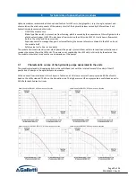
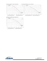
Страница 39: ...its own electric panel which powers the pumps protects them with motor overload protections and receives the consent from the LEW units The power is not supplied by the LEW unit but directly by the external line The module is insulated to reduce the sound emissions of the pumps 3 1 Characteristic curves of the hydraulic pumps associated to the units The graphics displayed in this paragraph show th...

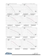
Страница 40: ...ps on utility side Useful head for LEW 141 142 144 pumps on utility side Useful head for LEW 161 162 164 pumps on utility side Useful head for LEW 181 182 184 pumps on utility side Useful head for LEW 204 pumps on utility side Useful head for LEW 214 pumps on utility side Useful head for LEW 243 244 pumps on utility side ...

Страница 41: ...ps on utility side Useful head for LEW 344 pumps on utility side Useful head for LEW 374 pumps on utility side Useful head for LEW 424 pumps on utility side Useful head for LEW 484 pumps on utility side Useful head for LEW 041 042 pumps on dissipation side Useful head for LEW 051 052 pumps on dissipation side ...

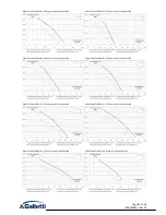
Страница 42: ...ation side Useful head for LEW 081 082 pumps on dissipation side Useful head for LEW 091 092 pumps on dissipation side Useful head for LEW 111 112 pumps on dissipation side Useful head for LEW 131 132 pumps on dissipation side Useful head for LEW 141 142 pumps on dissipation side Useful head for LEW 144 pumps on dissipation side ...

Страница 43: ... on dissipation side Useful head for LEW 204 pumps on dissipation side Useful head for LEW 214 pumps on dissipation side Useful head for LEW 243 pumps on dissipation side Useful head for LEW 244 283 284 pumps on dissipation side Useful head for LEW 314 pumps on dissipation side Useful head for LEW 344 pumps on dissipation side ...

Страница 44: ...Page 44 of 56 RG66006951 Rev 01 Useful head for LEW 374 pumps on dissipation side Useful head for LEW 424 pumps on dissipation side Useful head for LEW 484 pumps on dissipation side ...

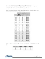
Страница 45: ...99 LEW 071 M1 395 HF64000799 LEW 072 M1 395 HF64000799 LEW 081 M1 395 HF64000799 LEW 082 M1 395 HF64000799 LEW 091 M1 399 HF64000799 LEW 092 M1 399 HF64000799 LEW 111 M1 399 HF64000799 LEW 112 M1 399 HF64000799 LEW 131 M1 412 HF64000799 LEW 132 M1 412 HF64000799 LEW 141 M1 412 HF64000799 LEW 142 M1 412 HF64000799 LEW 161 M1 433 HF64000799 LEW 162 M1 433 HF64000799 LEW 181 M1 543 HF64000799 LEW 182...

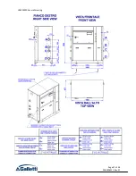
Страница 46: ...Page 46 of 56 RG66006951 Rev 01 3 3 Overall drawings of optional hydronic modules HF64000799 overall drawing ...

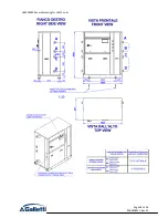
Страница 47: ...Page 47 of 56 RG66006951 Rev 01 HF64000906 overall drawing ...

Страница 48: ...Page 48 of 56 RG66006951 Rev 01 HF64000908 overall drawing for LEW C units ...

Страница 49: ...Page 49 of 56 RG66006951 Rev 01 HF64000908 overall drawing for LEW D W H units ...

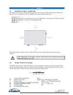
Страница 50: ... to the optional hydronic modules When installing the unit for safety purposes make sure that the room temperature does not exceed 50 C with unit on or off 4 2 Volume of water in the system The ON OFF type compressors work intermittently since the cooling power required by the utility is not generally the same as that supplied by the compressor In systems containing little water in which the therm...

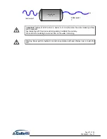
Страница 51: ...de type flow switch supplied Any tampering with this device will immediately invalidate the warranty We recommend installing a metal net filter on the water inlet piping Warning Never perform hydraulic connection operations with open flames near or inside the unit Inertial Tank Ts C Inlet water T Outlet water T ...

Страница 52: ...g point as shown in the following table Minimum temperature of produced water 5 C 2 C 1 C 5 C 10 C Percentage in weight of ethylene glycol 0 10 15 25 30 Freezing temperature of mixture 0 C 4 C 8 C 14 C 18 C If the water produced is below 0 C a special insulation needs to be applied to the cold pipes to prevent ice from forming This is why applications with temperatures produced below 0 C must be c...

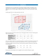
Страница 53: ...sure side of the circuit value which determines its limits for units with power outputs higher than 140 kW per circuit a second pressure switch sets the threshold to 40 5 bar 5 2 Water flow to evaporator The nominal flow rate is based on a temperature differential of 5 C between inlet and outlet water in relation to the cooling capacity provided at the nominal water 12 7 C temperatures The maximum...

Страница 54: ...e I Calibration of control devices Control device Set Point C Differential C Service thermostat C 12 2 Service thermostat H 40 2 Table II Calibration of safety devices Control device Unit of measurement Switching it on Differential Resetting Antifreeze thermostat C 4 2 Automatic Maximum pressure switch cat IV PED bar 40 5 Manual Low pressure safety valve cat IV PED bar 29 0 0 10 Minimum pressure s...

Страница 55: ...ater temperature reading at the chiller unit inlet water returning from the system Refer to the section of the document on the microprocessor control for further details Calibration of the antifreeze thermostat function The antifreeze probe is located at the evaporator outlet and stops the compressor if the water temperature drops below the preset limit Together with the flow switch and low pressu...

Страница 56: ...40010Bentivoglio BO Via Romagnoli 12 a Tel 051 8908111 Fax 051 8908122 www galletti it Azienda certificata UNI EN ISO 9001 e OHSAS 18001 ...

Отзывы: