Page
18
of
56
RG66006951
‐
Rev.01
1.4 Electric
panel
The
electric
panel
is
built
and
wired
in
accordance
with
standard
EN
60204
‐
1.
The
electric
panel
is
accessed
from
the
front
of
the
machine.
Before
it
can
be
accessed,
the
unit
must
be
disconnected
from
the
power
supply
using
the
main
switch,
which
functions
as
a
door
‐
lock.
All
the
remote
controls
are
implemented
with
low
voltage
signals
at
24
V,
powered
by
an
isolation
transformer
positioned
inside
the
control
board.
All
the
control
boards
have
an
air
circulation
system
with
auxiliary
fans.
The
position
of
the
main
switch
makes
wiring
operations
in
the
work
site
easier.
This
avoids
several
difficult
operations
as
well
as
having
to
twist
the
power
cords.
All
the
utilities
are
protected
against
surges
and
short
circuits.
The
circuit
breaker
set
‐
up
can
be
configured
for
any
load
(optional).
Thermal
protection,
however,
is
carried
out
by
thermistor
chains.
These
are
set
in
the
windings
of
each
electric
motor
and
are
controlled
by
onboard
electronics.
All
machines
are
standard
‐
equipped
with
a
phase
sequence
relay
which
inhibits
compressor
operation
if
the
phase
sequence
is
not
carried
out:
only
one
direction
of
rotation
is
possible
for
scroll
compressors,
as
well
as
for
the
screw
and
Rotary
compressors.
The
unit
is
rated
IP43
which
makes
it
suitable
for
outdoor
installation.
The
control
board
with
the
open
panel
maintains
an
IP20
rating.
Inside
the
electrical
control
board
of
the
Basic
control
there
are
two
manual
selectors
to
enable
remote
switching
on
‐
off,
seasonal
changeover
(only
heat
pumps)
and
to
select
local
or
remote
control:
remote
consents
are
implemented
by
very
low
voltage
contacts
placed
on
the
terminal
board.
1.4.1
Control
microprocessor
LEW
series
units
have
two
different
microprocessor
control
levels:
‐
Basic
–
Carel
µChiller
‐
Advanced
–
Carel
series
pCO
The
latter,
in
addition
to
the
functions
described
below,
can
customise
the
software
to
meet
all
system
requests.
These
include
cascade
management
of
the
units
with
step
‐
control
or
cascade
logic.
The
microprocessor
on
board
the
unit
controls
the
various
operating
parameters
with
an
electric
panel
keypad;
‐
Compressor
connection/disconnection
to
maintain
the
set
‐
point
of
the
chiller
inlet
water
T;
‐
Alarm
management:
High
/
low
pressure;
Antifreeze
/
Flow
switch;
Pump
alarm
‐
Alarm
signals
‐
Display
of
operating
parameters
‐
Evaporator
anti
‐
freeze
protection
‐
Control
of
maximum
number
of
compressor
starts
‐
RS232,
RS485
serial
output
control
(optional)
‐
Incorrect
phase
sequence
(not
viewed
on
display,
prevents
the
compressor
from
starting)
As
for
remote
communication,
the
controls
can
be
connected
to
advanced
BMS
systems.
The
HSD
(HiRef
Software
Department)
structure
is
capable
of
assisting
customers
in
integration
operations.
System
interconnectivity
capabilities
are
summarised
below:
‐
Available
serial
ports
‐
RS232
‐
RS485
‐
Ethernet
(“HiWeb”
board)
‐
GSM
Modem:
with
prepaid
card
and
relative
antenna
on
board
the
machine
for
autonomous
two
‐
way
control
of
alarms
and/or
set
‐
point
variations
‐
Protocols
‐
Carel
[Built
‐
In]
‐
Modbus®
[Built
In
with
Advanced
controls]
‐
Modbus®
[With
external
gateway
with
Basic
controls]
‐
LonWorks®
[Dedicated
serial
board
to
be
requested
when
ordering
the
machine]
‐
BACnet™
[With
external
gateway]
‐
TCP
‐
IP
[With
external
gateway]
‐
TREND®
[Dedicated
serial
board
to
be
requested
when
ordering
the
machine]
(ref.
Microprocessor
control
manual
for
further
details)
Содержание LEW CD
Страница 1: ...GB Technical manual LEW Reversible Chillers and Heat Pumps LEW SERIES 40 420 kW ...
Страница 2: ...Page 2 of 56 RG66006951 Rev 01 ...
Страница 17: ...Page 17 of 56 RG66006951 Rev 01 Reference table for numbering used in layouts ...
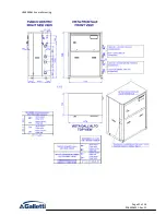
Страница 30: ...Page 30 of 56 RG66006951 Rev 01 2 4 Overall drawings of the main units HF64000737 overall drawing ...
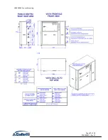
Страница 31: ...Page 31 of 56 RG66006951 Rev 01 HF64000614 overall drawing ...
Страница 32: ...Page 32 of 56 RG66006951 Rev 01 HF64000592 overall drawing ...
Страница 33: ...Page 33 of 56 RG66006951 Rev 01 HF64000608 overall drawing ...
Страница 34: ...Page 34 of 56 RG66006951 Rev 01 HF64000581 overall drawing ...
Страница 35: ...Page 35 of 56 RG66006951 Rev 01 HF64000609 overall drawing ...
Страница 36: ...Page 36 of 56 RG66006951 Rev 01 HF64001344 overall drawing ...
Страница 37: ...Page 37 of 56 RG66006951 Rev 01 HF64000803 overall drawing ...
Страница 38: ...Page 38 of 56 RG66006951 Rev 01 HF64000627 overall drawing ...
Страница 46: ...Page 46 of 56 RG66006951 Rev 01 3 3 Overall drawings of optional hydronic modules HF64000799 overall drawing ...
Страница 47: ...Page 47 of 56 RG66006951 Rev 01 HF64000906 overall drawing ...
Страница 48: ...Page 48 of 56 RG66006951 Rev 01 HF64000908 overall drawing for LEW C units ...
Страница 49: ...Page 49 of 56 RG66006951 Rev 01 HF64000908 overall drawing for LEW D W H units ...


