background image

4

   |  Part Number: 3E2453 R1

Installation Note  |  Gallagher T10 Mifare Reader

Using the drill template at the back of this installation note as a 

1. 

guide, drill all three holes.  Drill the 13mm (1/2 inch) diameter centre 
hole (this is the centre hole for which the building cable will exit the 
mounting surface) and the two fixing holes.

Run the building cabling out through the centre hole and through the 

2. 

reader base.

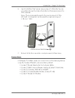
Secure the base to the mounting surface using the two fixing screws 

3. 

provided.  It is important the base of the reader is flush with and tight 
against the mounting surface.

Note:  Ensure the centre hole allows the cable to run freely out through 
the mounting surface, so that the reader facia can clip into the base.


Base

6 Gauge screw

Building cable

6 Gauge screw

Connect the reader tail extending from the facia assembly to the 

4. 

building cable.  Connect the wires shown below.

Note:  Do not cut the ‘Reserved’ wires, they may be required later.


Positive

Red

Negative

Black

Reserved

Orange

Reserved

Green

Reserved

Brown

CDXIV TX

White

CDXIV RX

Blue

Cardax IV Reader

Fit the facia assembly into the base by clipping the small lip, into the 

5. 

top of the base and holding the top, press the bottom of the facia 
assembly down into the base.

Содержание T10

Страница 1: ...SFire EV1 Mifare Plus and Mifare Classic cards The reader sends information to the Cardax FT Controller and acts upon information sent from the Cardax FT Controller The reader itself does not make any...

Страница 2: ...should be linear or a good quality switched mode power supply The performance of the reader may be affected by a low quality noisy power supply Cabling The Gallagher T10 Mifare reader requires a mini...

Страница 3: ...al wall check that any reader fixed to the other side of the wall is not less than 200mm 8 inches away Wall thickness less than 200mm 200mm Installation The Gallagher T10 Mifare reader is designed to...

Страница 4: ...he reader is flush with and tight against the mounting surface Note Ensure the centre hole allows the cable to run freely out through the mounting surface so that the reader facia can clip into the ba...

Страница 5: ...orque of 1 5Nm 1 1 lb ft Fit screw to secure facia to base Facia Building cable Reader tail Connection Removal of the facia assembly is a simple reversal of these steps 7 Connections A Gallagher T10 M...

Страница 6: ...x IV Reader 1 Connecting to the Cardax FT GBUS Universal Reader Interface Connect the wires to the sockets as shown in either of the following diagrams RLY 2 COM RLY 2 NO RLY 2 NC DATA 0 DATA 1 OUT 1...

Страница 7: ...rs into the Cardax FT Command Centre system The ports to which the Gallagher T10 Mifare reader can connect are set up as groups as follows Two groups numbered 1 and 2 on the Controller 3000 4R and Fou...

Страница 8: ...T 2 PB PA Positive Red Negative Black Reserved Orange Reserved Green Reserved Brown CDXIV TX White CDXIV RX Blue Cardax IV Reader Positive Red Negative Black Reserved Orange Reserved Green Reserved Br...

Страница 9: ...vironmental regulations for the Restriction of Hazardous Substances in electrical and electronic equipment RoHS The RoHS directive prohibits the use of electronic equipment containing certain hazardou...

Страница 10: ...is no guarantee that interference will not occur in a particular installation If this equipment does cause harmful interference to radio or television reception which can be determined by turning the...

Страница 11: ...Drill Template 115mm 4 53 inches 35mm 1 38 inches 44mm 1 73 inches 40mm 1 57 inches 13mm 1 2 inch diameter hole for cable 22 5mm 0 89 inches 40mm 1 57 inches...

Отзывы: