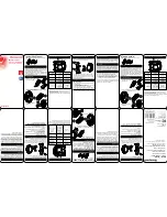
Step 1.
• Fold template where indicated.
• Position template on door edge at
desired lock / latch height.
• Firmly hold template and mark latch
height and 54mm (2 1/8") lock body
hole centre.
• Measure door thickness and mark
centre on 'latch height' marking.
• Drill 22mm (7/8") latch hole.
Note:
it is important to drill this
hole squarely.
• Drill pilot hole for lock body
[suggested size 3mm (1/8")]. Then
enlarge holes to 54mm (2 1/8"),
drilling from both sides of the door.
Step 3.
• Insert the latch through the slot in the carrier until it can go no further.
• Insert the key and turn to retract the latch bolt.
• Pre-drill wood screw holes with suitable drill size.
• Install plastic faceplate shim and faceplate, then screw into position.
Step 2.
• Mark and chisel latch faceplate
to a recess of 3.5mm.
Use latch carrier as a template.
• Insert lock body into 54mm
(2 1/8") hole.
• Insert latch carrier through
22mm (7/8") hole into lock body
assembly and tighten with 2
screws.
Ensure T-shaped hole at rear
of latch carrier is upright!
Please note:
Ensure the template
position and orientation is as shown,
incorrect installation voids warranty.
NOTE: • carefully follow these instructions when installing.
• do not overtighten screws.
• use of power driver is not recommended.
• fully remove the Trilock prior to painting the door
to avoid harming the product's finish.
T890PKD02UM1
JUL ‘13
T-Shape hole
Rear view
of latch
Latch
carrier
Double Cylinder
Lock body
DO NOT REMOVE
square spindle
Do not remove
(If aligning template has been removed
turn square spindle away from the latch
bolt housing as far as it can go before
inserting the latch bolt).
Step 4
• Remove perforated cut-out from cardboard
template and place over lock body, making
sure template is square to door edge.
• While holding template firmly in position, mark
remaining 5 holes, as indicated on both sides
of the door (reversing template as required).
• Drill pilot holes from both sides of the door
[suggested size 3mm (1/8")] then enlarge,
again from both sides of the door, to sizes
indicated on template, otherwise correct
functioning may be impeded – refer template.
• In particular, ensure the 54mm
(2 1/8") dia. hole through door face (located
above lock body hole) is drilled only to
correct size, otherwise correct functioning
may be impeded–refer template.
Note: Top 54mm hole must have burrs
removed before installing Trilock as this
will effect snib rotor operation & privacy
function.
1
2
3
4
1. Remove latch bolt assembly from carrier
4. Rotate bolt 180˚
5. Re-attach arm to latch bolt
6. Rotate arm upwards &
fit back into carrier
2. Rotate arm downwards
3. Unclip arm from latch bolt
Arm
Rotate bolt 180˚
Step 3a
Trilock Latch Bolt re-handing.
• Check that tapered side of the latch bolt faces towards the door jamb.
• If not it will be necessary to unclip the rear arm & rotate bolt 180˚.
• This is achieved by following steps:
Please note:
For the single cylinder Trilock version,
the turnbutton stem should be on the
internal side of the door.
If this is not the case, please re-hand
the lock body.
To re-hand: remove the grub screw with
allen key provided, remove and turn the
cylinder to desired direction and re-install.
Re-fasten grub screw with allen key.
Turnbutton
stem
Latch carrier screws
Installation Instructions for Trilock Traditional & Contemporary Series
– Double & Single Cylinder
These instructions apply to both Lever and Knob versions


