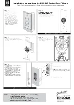
Step 7
• Install 2 posts to Trilock external faceplate
(this is the faceplate
without
the r
ectangular snib
push-button).
Step 8
• Mount the Inside face plate so that
mark on large gear engages with mark
on lock bodygear
NOTE:
•
carefully follow these instructions when installing.
•
do not overtighten screws.
•
use of power driver is not recommended.
•
fully remove the Trilock prior to painting the door
to avoid harming the product's finish.
Step 5
• Remove perforated cut-out from
card-board template and place over
lock body, making sure template is
square to door edge.
• While holding template firmly in
position, mark remaining 3 holes, as
indicated on both sides of the door
(r
eversing template as required).
• Drill pilot holes from both sides of the
door [suggested size 3mm (1/8")] then
enlarge, again from both sides of the
door, to sizes indicated on template,
otherwise correct functioning may be
impeded – refer template.
Step 6
To rehand external lever & set
lever operation (if required).
• If rehanding is required remove the stop
screw from SS1 & fit to SS2, to allow Lever
to operate away from door edge
NOTE:
There is no need to rehand the internal lever.
NOTE:
These steps are applicable to leverset only.
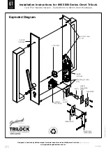
Step 9
• Insert spring and snib rotor in the square hole
of the internal lever
.
• Position snib rotor so one notch faces up and
the other notch points to the latch side.
• Mount outside furniture plate to outside of the
door, and align the two making sure the snib
rotor engages with the external lever
.
• Fit mounting screws from inside and tighten
into threaded posts.
• Fit wood screws 3 off to inside furniture plate
(recommend pilot drilling before fitting screws).
NOTE:
T
est all functions for smooth operation.
SS2
SS1
1
3
2
Note:
Position Snib Rotor so one notch faces
up & the other notch points to the door edge.
Mounting screws (2 off)
Wood screws (3 off)
Installation Instructions for 8955 BB Series Omni Trilock
Twin Pull Handle Version - Suits 35mm to 45mm door thickness


