Pub. 42004-489D
Model 354-001 Series NEMA 4X Industrial Telephone
Page 7 of 10
f:\standard ioms - current release\42004 instr. manuals\42004-489d.doc
01/15
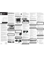
Ring Relay Wiring
1.
Connect the incoming subscriber line to the TB1 terminal block. See Figure 5.
2.
Connect the external sounder or beacon to TB2 for activation with an incoming telephone call. See
Figure 5 and Figure 6.
3.
Before reattaching the panel assembly, connect the USOC RJ11C modular connector cord (provided
with the Ring Relay Kit) from the Industrial Telephone PCBA to the Ring Relay PCBA.
Figure 5. Ring Relay PCBA Wiring
Figure 6. Device Interconnection