background image

Pub. 42004-308G 

Model 234WM-202 Wall-Mount Stanchion Assembly 

Page 5 of 11 

p:\standard ioms - current release\42004 instr. manuals\42004-308g.docx 
04/16 

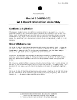
Tempered Glass Installation (Factory Installed) 

1.


Remove the keps nuts, spacer brackets, and holding brackets.  These parts will be used for holding the 
glass in place. 

2.


Carefully unpack the glass from the box located in the telephone mounting area of the Model 
234WM-202 Wall-Mount Stanchion. 

3.


Center the front glass left to right and top to bottom around the opening in the front panel assembly 
and fasten in place using the spacer brackets, holding brackets, and keps nuts removed previously.  
Refer to Figure 4 for assembly details. 

N

OTE

:

  Do not exceed 24 inch-pounds of torque on the keps nuts. 

4.


Repeat the above steps for both side glass pieces. 


Figure 4.  Glass Installation Instructions 

Содержание 234WM-202

Страница 1: ...ommunications station and is designed to house a GAI Tronics Model 39x or 27x Series Flush Mount Telephone and a Model 540 001or 531A Strobe each sold separately The stanchion is a simple attractive y...

Страница 2: ...ly Page 2 of 11 p standard ioms current release 42004 instr manuals 42004 308g docx 04 16 Installation The following sections provide information on the installation of the complete wall mount stanchi...

Страница 3: ...r sold separately is required to remove the tamper resistant screws 2 Remove the wall mounting assembly from the front panel assembly Refer to Figure 1 Detach the chain from the wall mounting assembly...

Страница 4: ...ccordance with the National Electrical Code NEC in the United States or the Canadian Electrical Code CEC in Canada A 10 grounding stud has been provided at the base of the stanchion for grounding Conn...

Страница 5: ...refully unpack the glass from the box located in the telephone mounting area of the Model 234WM 202 Wall Mount Stanchion 3 Center the front glass left to right and top to bottom around the opening in...

Страница 6: ...wires will be connected later along with the strobe wires to the incoming power wires in accordance with the electrical codes Model 84503 302 Extend the black and the white wires to the base of the s...

Страница 7: ...nstallation 1 Insert the strobe s seven 15 foot wires through the stanchion s threaded nipple and allow the wires to extend to the bottom of the stanchion See Figure 6 2 Screw the strobe onto the thre...

Страница 8: ...elf tapping flat head screws Refer to Figure 7 below The telephone back box has two openings one in the top and one in the bottom Plug the top opening with the hole plug The bottom of the back box is...

Страница 9: ...wired to the telephone this cable can be removed and discarded 9 Attach the telephone cable from the surge protector to TB1 on the telephone PCBA as shown in Figure 8 10 Attach the strobe s violet an...

Страница 10: ...Sol or equivalent Allow the area to dry This type of product is normally available at auto parts stores Denatured alcohol may also be used 3 Prepare the bare metal surface for painting by treating it...

Страница 11: ...5 in Wall material Aluminum Finish Textured powder coat epoxy Power ratings Model 540 001 AC Strobe 0 39 A 120 V ac Model 531A DC Strobe 2 7 A 24 V dc Model 84503 301 AC Panel Light Assembly 25 mA 120...

Страница 12: ...of the Contractor s personnel from the work site Re performance of services shall be Buyer s sole and exclusive remedy and in no event shall GAI Tronics warranty obligations with respect to services e...

Отзывы: