


Outdoor Microphone System - Page 18
G.R.A.S. Sound & Vibration
5.3
Multi-frequency Calibration Check (Optional)
This makes use of an option which calls for an internal modification of the Outdoor Microphone
System.
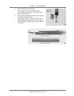
This option allows an AC signal of approximately 1 V RMS to be applied to pin 4 shown in
Fig. 5.2. This signal is led to the calibration circuit for amplification and then applied to the sys
-
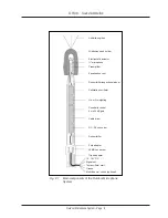
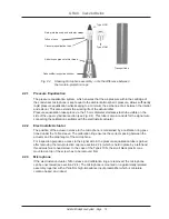
tem’s electrostatic actuator built into the rain-protection cap (see Fig. 2.4). As with the system’s
own calibration oscillator, frequency doubling will take take place.
This option is useful for checking the stability of the system’s frequency response. It is not a
measure of its free-field frequency response.
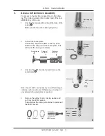
5.3.1 Output Connections
The output connections via the LEMO socket at the base of the Outdoor Microphone System
are shown in Fig. 5.2.
Fig. 5.2 LEMO socket output connections (external view)


