


Section 50
00-02-0271
2018-10-23
-
11 -
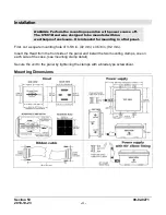
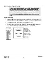
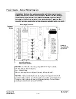
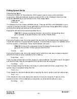
Power Supply
– Typical Wiring Diagram
WARNING:
Perform the wiring operation with the power source
“OFF” and the area made non-hazardous. Make sure the voltage
and current requirements are within the S1501 system ratings.
Conduit is required to protect wires from damage. Refer to the
specific system application wiring diagram supplied with your unit.
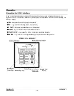
NOTE 1:
K-1 thru K-
7 are relay outputs form “C” dry contacts.
D1 thru D8 are LED indicators.
D1= POWER ON;
D2=K1; D3=K2; D4=K3; D5=K4; D6=K5; D7=K6; D8=K7.
NOTE 2:
Opto-isolated tach/run input jumper is shipped in the IGN
position. IGN socket is used for negative or positive ground type CD
ignitions. MPU socket is used for magnetic pickup or motor starter
auxiliary contact not to exceed 120 Vrms.
Содержание Selectronic S1501 series
Страница 4: ...THIS PAGE INTENTIONALLY LEFT BLANK...
Страница 9: ...Section 50 00 02 0271 2018 10 23 5...
Страница 33: ...Section 50 00 02 0271 2018 10 23 29...
Страница 34: ......


